
Foot joint supporter

a supporter and foot technology, applied in the field of ankle supporters, can solve the problems of osteocartilage injury, often stretched or torn ligaments, etc., and achieve the effects of improving stability, improving the conformity of the talocrural joint, and reducing the risk of ankle sprain

Active Publication Date: 2016-07-21
OPTI INC
View PDF3 Cites 21 Cited by
  • Summary
  • Abstract
  • Description
  • Claims
  • Application Information

AI Technical Summary

Benefits of technology

The ankle supporter described in this patent helps to prevent ankle sprains by improving the movement and stability of the ankle joint. This is achieved by applying tension to a panel that connects the ball of the foot and medial malleolus, which reduces the risk of the talus bone shifting during dorsiflexion (bending) of the ankle joint. This improves the conformity of the talocrural joint and ensures the ankle joint is stable and secure.

Problems solved by technology

The lateral ligaments are often stretched or torn, and osteocartilage injury can occur.

Method used


Image

  • Foot joint supporter
  • Foot joint supporter
  • Foot joint supporter

Examples


first embodiment

of the Invention

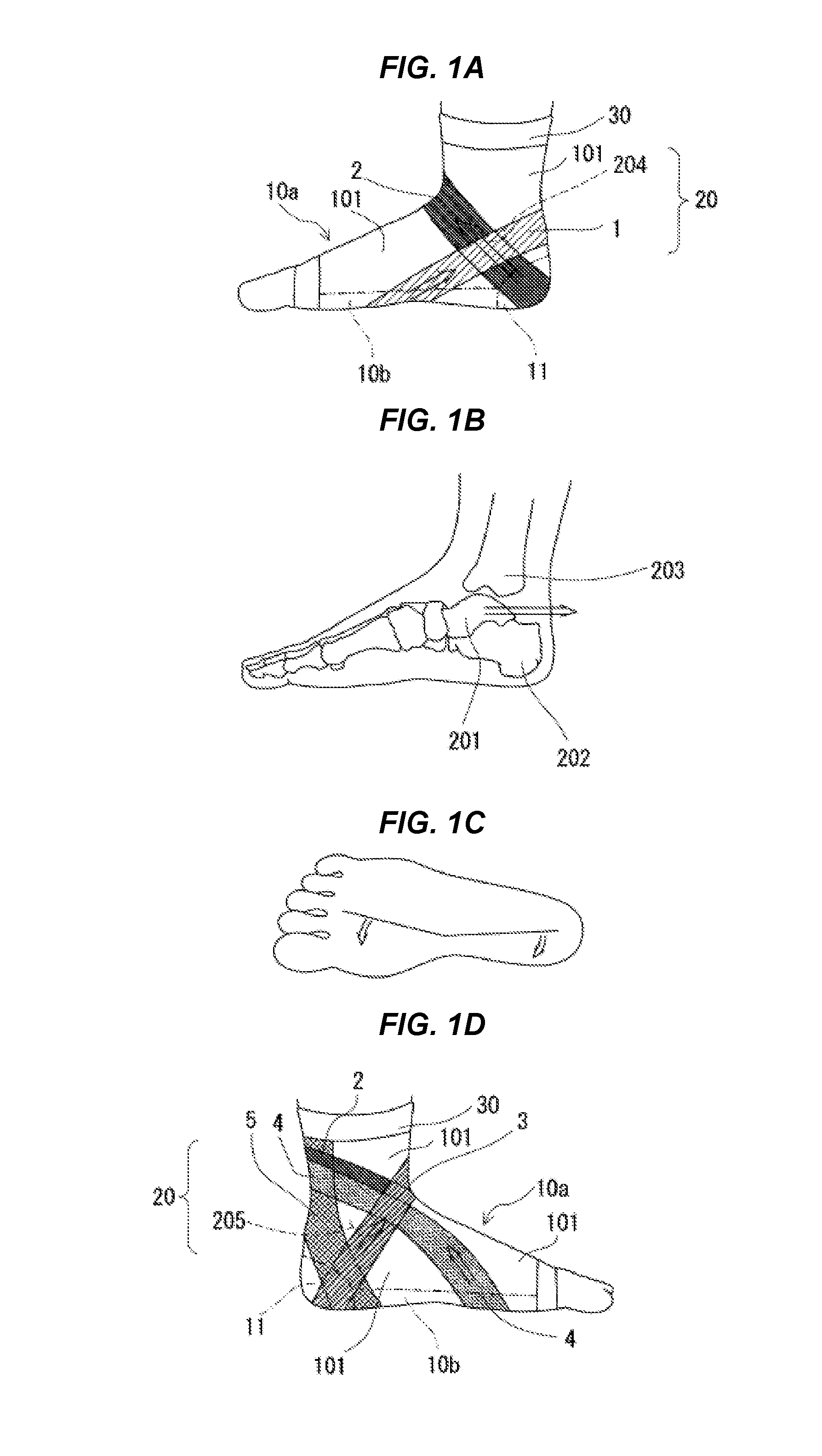
[0018]A right ankle supporter 100 will be described below with reference to FIG. 1. However, since the left ankle supporter 100 differs from the right ankle supporter 100 only in that the first elastic panel 1, second elastic panel 2, third elastic panel 3, fourth elastic panel 4, and fifth elastic panel 5 of the left ankle supporter are bilaterally symmetrical to those of the right ankle supporter, the left ankle supporter will not be shown in the drawings.

[0019]Further, in FIG. 1, a supporter with an open toe is shown as the ankle supporter 100, but a sock-type supporter with a closed toe bag may be used.

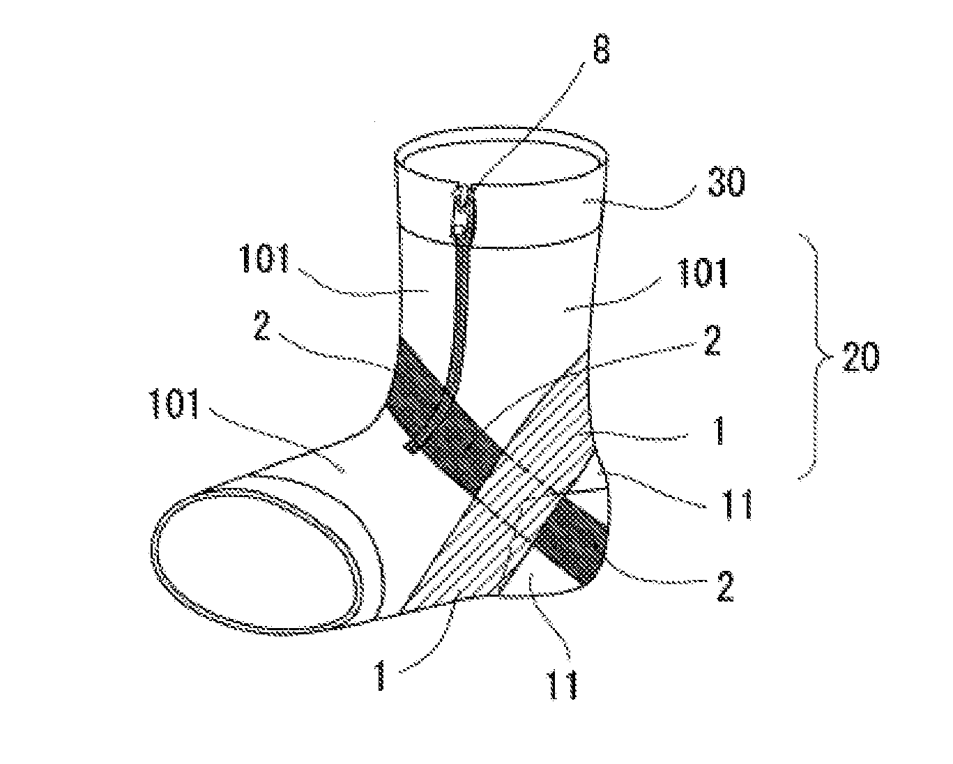
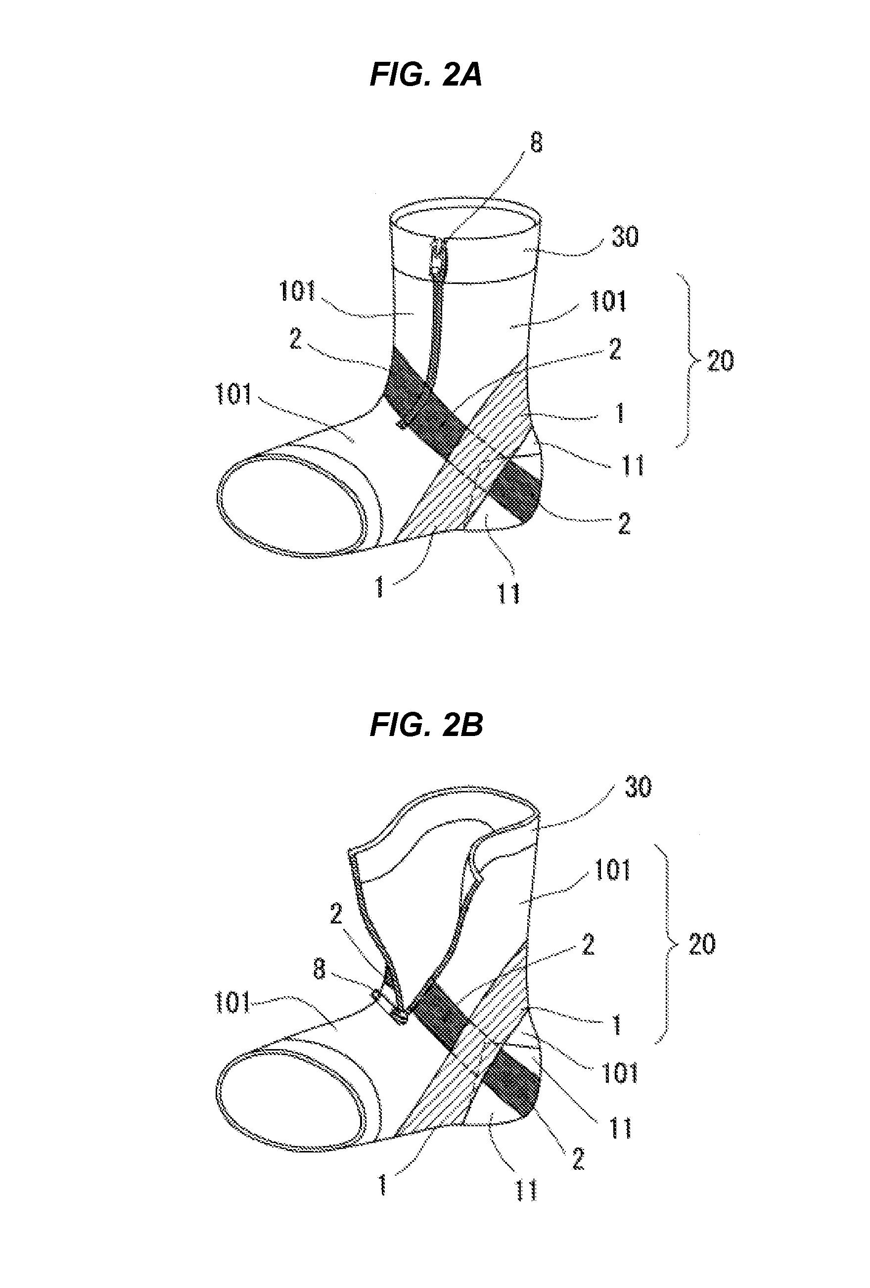
[0020]Further, the ankle supporter 100 may include a zipper 8 (a fastener) used to open and close the body 20 at the top as shown in FIG. 2, and a hook-and-loop fastener, lacing, or a magic belt (trademark) may be used instead of the zipper 8.

[0021]According to the embodiment shown in FIG. 1(a), the ankle supporter 100 surrounds at least the wearer's ankle with a b...

example

[0038]Next, we present an application of the theory described above to a subject wearing socks 100a produced by circular knitting according to the design of ankle supporter 100. FIGS. 3 to 5 are shown as references.

[0039]In the description below, the right sock 100a will be described with reference to FIGS. 3 to 5. Since the left sock 100a differs from the right sock only in that the knitted fabric positions of the first elastic panel 1, the second elastic panel 2, the third elastic panel 3, the fourth elastic panel 4, and the fifth elastic panel 5 are bilaterally symmetrical to those of the right sock 100a, the left socks will not be shown in the drawings.

[0040]According to the embodiment shown in FIGS. 3 and 4, sock 100a is produced on a sock knitting machine using knitting yarns including a front yarn, a rear yarn, and a rubber yarn. The sock-knitting machine used in this example was “Lambda Infini” (number of stitches: 144), manufactured by Murata Manufacturing Co., Ltd. Here, a...


PUM


Abstract

Provided is an ankle supporter capable of returning the wearer's ankle to a normal position by moving the connective tissue and muscles below the skin following sprain or Achilles tendonitis. The ankle supporter includes a first elastic panel knitted in a belt-like shape on the medial side of the wearer's foot extending from the sole to an area corresponding to the Achilles tendon and having a stretch resistance greater than that of the base fabric and a second elastic panel knitted in a belt-like shape on the medial side of the wearer's foot extending from the heel to the base of the foot top of the wearer to intersect the first elastic panel below the center of the medial ankle and having a stretch resistance greater than that of the base fabric.

Description

TECHNICAL FIELD[0001]The present invention relates to an ankle supporter.BACKGROUND[0002]The ankle joint includes the talocrural and subtalar joints, which connect the calcaneus with the talus and the talus with the lower leg bones composed of the tibia and fibula, respectively. Ankle sprain is an injury that frequently occurs in sports. Following injury, the medial aspect of the talus often exhibits reduced posterior gliding during ankle dorsiflexion (extension). The lateral ligaments are often stretched or torn, and osteocartilage injury can occur. Therefore, there has been a demand to develop a supporter or a brace that can effectively prevent ankle sprain.[0003]A pair of socks of the prior art may be obtained by setting a first structure that can apply tension in the wale direction extending from a position behind the ball of the foot at the sole of the socks to a position that includes the boundary between the arch and the heel, setting a second structure that can apply increas...

Claims


Application Information

Patent Timeline
IPC IPC(8): A61F5/01
CPCA61F5/0111
Inventor IIDA, TAKUJI
Owner OPTI INC
Learn More