Low-profile cavity broadband antennas having an anisotropic transverse resonance condition

a broadband antenna and low-profile cavity technology, applied in the field of broadband antennas, can solve the problems of difficult to match a high dielectric material, general bandwidth limitation, and inability to achieve the effect of high dielectric material density and low cos

Active Publication Date: 2016-07-14
UNITED STATES OF AMERICA THE AS REPRESENTED BY THE SEC OF THE ARMY
View PDF13 Cites 0 Cited by
  • Summary
  • Abstract
  • Description
  • Claims
  • Application Information

AI Technical Summary

Benefits of technology

[0014]Depending on operation, the antenna may be feed with a just single input port. Or, in other embodiments, the antenna may be fee...

Problems solved by technology

However, these are generally bandwidth limited due to the fact that it is very difficult to match a high dielectric material over more than a narrow band.
Using antenna image theory, a PMC ground plane allows an antenna to approach the ground plane without cancelling out its radiation...

Method used


Image

  • Low-profile cavity broadband antennas having an anisotropic transverse resonance condition
  • Low-profile cavity broadband antennas having an anisotropic transverse resonance condition
  • Low-profile cavity broadband antennas having an anisotropic transverse resonance condition

Examples


Embodiment Construction

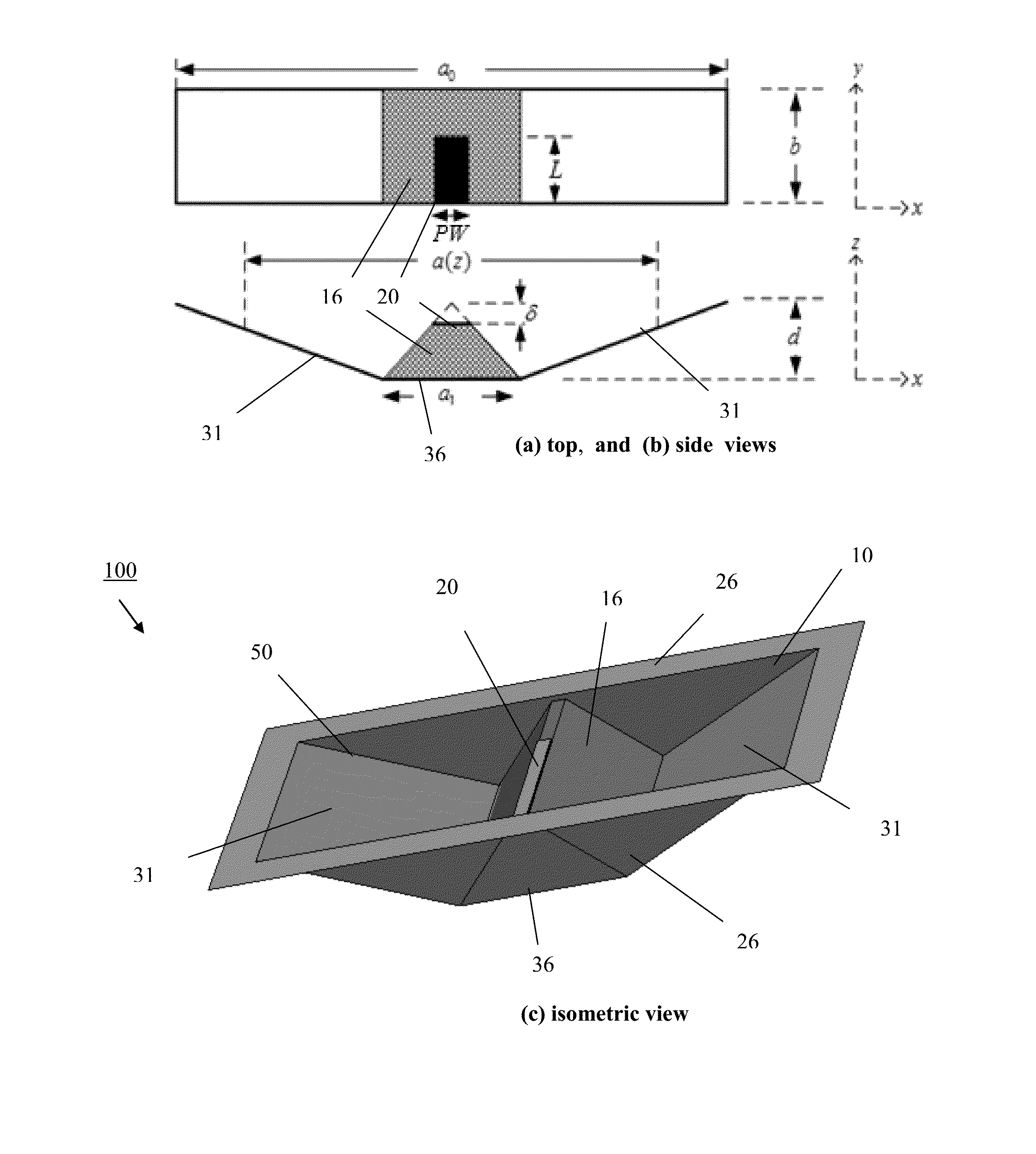
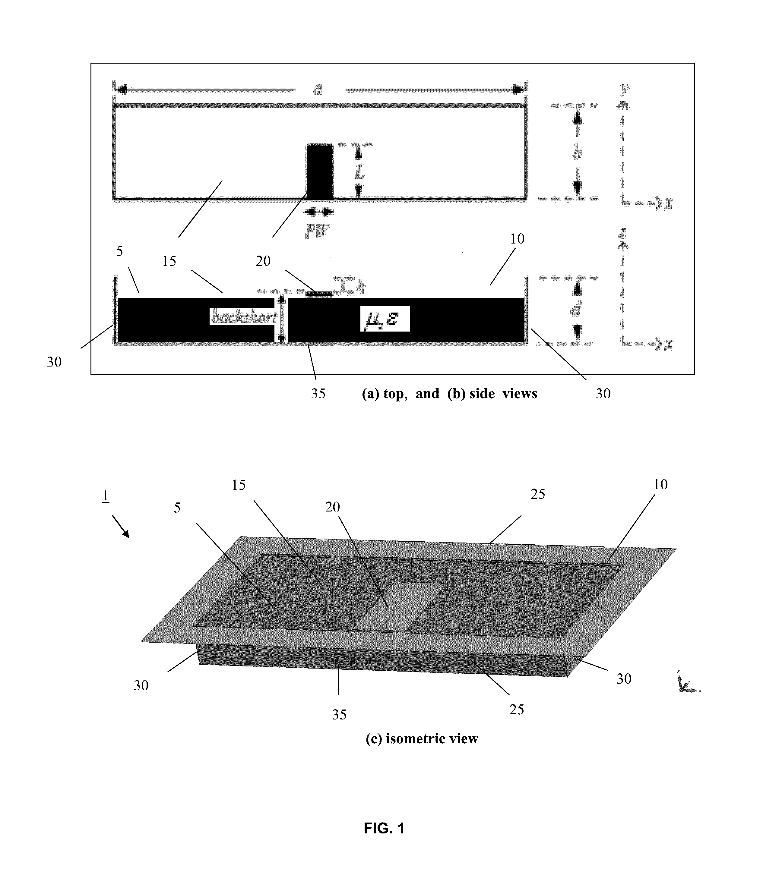
[0035]The present invention provides low-profile cavity broadband antennas having an anisotropic traverse resonance condition. As mentioned above, one important aspect of the invention is the incorporation of an anisotropic high index medium material, at least partially loaded within the cavity. This advantageous feature enables the antenna to maintain a constant resonance frequency within the cavity.

[0036]In some embodiments, the cavity may have tapered lateral sidewalls. Although, results show that the shape of the cavity can be changed as needed with no degradation to the overall antenna performance through control of the permeability in the normal direction μz.

[0037]Before describing embodiments of the present invention, this disclosure first details the derivation of a low profile cavity antenna by the inventors based on an anisotropic traverse resonance condition of a partially loaded cavity. This novel antenna cavity design is specifically designed to maintain a constant reso...


PUM


Abstract

Embodiments of the present invention relate to low-profile broadband antennas having an anisotropic traverse resonance condition. One important aspect of the invention is the incorporation of an anisotropic high index medium material, at least partially loaded within the cavity, which is configured to maintain a constant resonance frequency of the antenna. A low-profile cavity antenna may comprise: an aperture defining an opening to a cavity; an interior space defined by the cavity which is formed of a flat bottom wall defining a ground plane, and a pair of spaced-apart, lateral sidewalls extending away from the flat bottom wall in opposite directions toward the aperture; and an anisotropic high index medium material, at least partially loaded within the cavity, configured to maintain a constant resonance frequency of the antenna. The lateral sidewalls may extend from opposing sides of the flat bottom wall perpendicularly or with an outwardly taper.

Description

RELATED APPLICATION(S)[0001]This patent application is related to U.S. patent application Ser. No. 14 / 593,292 filed Jan. 9, 2015, titled “Low-Profile, Tapered-Cavity Broadband Antennas.” (Attorney Docket No. ARL 14-45), herein incorporated by reference in its entirety.GOVERNMENT INTEREST[0002]Government Interest—The invention described herein may be manufactured, used and licensed by or for the U.S. Government.BACKGROUND OF THE INVENTION[0003]I. Field of the Invention[0004]Embodiments of the present invention relate to broadband antenna, and more particularly, to low-profile cavity broadband antennas having an anisotropic traverse resonance condition.[0005]II. Description of the Related Art[0006]High index dielectric ceramics have been used to create low profile antennas at low UHF bands, for instance. However, these are generally bandwidth limited due to the fact that it is very difficult to match a high dielectric material over more than a narrow band. This stems from the fact tha...

Claims


Application Information

Patent Timeline
IPC IPC(8): H01Q9/04H01Q1/38
CPCH01Q1/38H01Q9/04H01Q9/0407H01Q13/02H01Q19/06H01Q19/10
Inventor MITCHELL, GREGORY A.WASYLKIWSKYJ, WASYL
Owner UNITED STATES OF AMERICA THE AS REPRESENTED BY THE SEC OF THE ARMY
Why Eureka
Try Eureka