
Optimized scale factor for frequency band extension in an audio frequency signal decoder

Active Publication Date: 2016-07-14
KONINKLJIJKE PHILIPS NV
View PDF11 Cites 12 Cited by
  • Summary
  • Abstract
  • Description
  • Claims
  • Application Information

AI Technical Summary

Benefits of technology

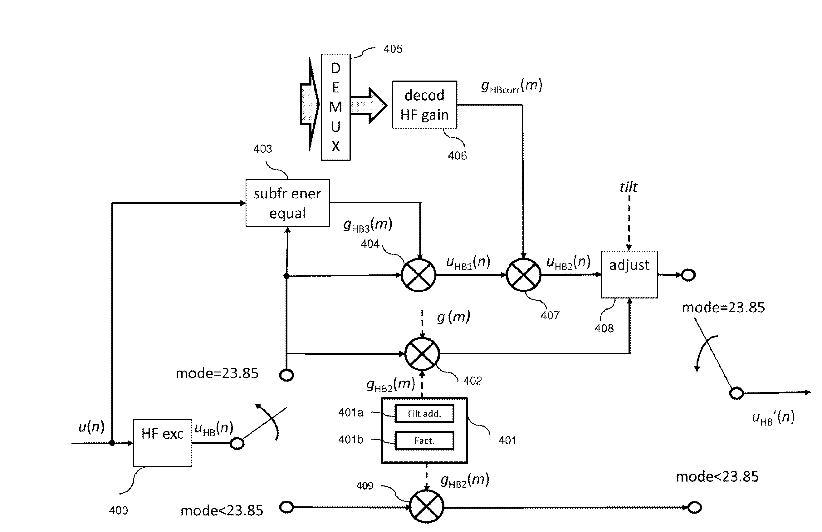
The invention improves the quality of a signal decoded at a lower bit rate compared to a different bit rate. This is possible because the invention uses additional information received at the higher bit rate to improve the quality of the signal at the lower bit rate. This improves the overall quality of the signal and allows for better control over the signal at the lower bit rate. The invention uses a method to determine an optimized scale factor, which helps to improve the quality of the signal. The method involves decoding or extracting parameters of a first frequency band, called the low band, and using them to determine a linear prediction filter called an additional filter. This additional filter is designed to improve the quality of the signal in a second frequency band, called the high band. The coefficients of this filter can be modified based on a stability criterion.

Problems solved by technology

However, in theory, it is well known that a signal sampled at 16 kHz can have a defined audio band from 0 to 8000 Hz; the AMR-WB codec therefore introduces a limitation of the high band by comparison with the theoretical bandwidth of 8 kHz.
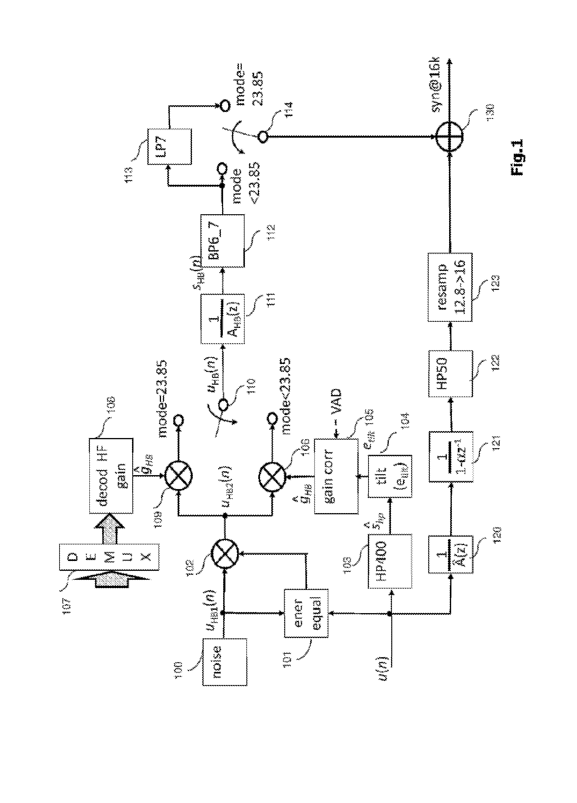
A number of drawbacks in the band extension technique of the AMR-WB codec can be identified, in particular:the estimation of gains for each subframe (block 101, 103 to 105) is not optimal.
However, it is in practice possible to verify that the direct equalization of the level between the two LPC filters at the separation frequency is not an optimal method and can provoke an overestimation of energy in high band and audible artifacts in certain cases; it will be recalled that an LPC filter represents a spectral envelope, and the principle of equalization of the level between two LPC filters for a given frequency amounts to adjusting the relative level of two LPC envelopes.
Now, such an equalization performed at a precise frequency does not ensure a complete continuity and overall consistency of the energy (in frequency) in the vicinity of the equalization point when the frequency envelope of the signal fluctuates significantly in this vicinity.
The risk in ensuring a spot continuity between low and high band LPC envelopes is of setting the LPC envelope in high band at a relative level that is too strong or too weak, the case of a level that is too strong being more damaging because it results in more annoying artifacts.
Furthermore, for the bit rates strictly less than 23.85 kbit / s, the compensation of levels of LPC filters in low and high bands can be applied in the band extension of a decoding compatible with AMR-WB, but experience shows that this sole technique derived from the AMR-WB+ coding, applied without optimization, can cause problems of overestimation of energy of 3.0 the high band (>6 kHz).

Method used


Image

  • Optimized scale factor for frequency band extension in an audio frequency signal decoder
  • Optimized scale factor for frequency band extension in an audio frequency signal decoder
  • Optimized scale factor for frequency band extension in an audio frequency signal decoder

Examples


Embodiment Construction

[0075]FIG. 3 illustrates an exemplary decoder, compatible with the AMR-WB / G.722.2 standard in which there is a band extension comprising a determination of an optimized scale factor according to an embodiment of the method of the invention, implemented by the band extension device illustrated by the block 309.

[0076]Unlike the AMR-WB decoding which operates with an output sampling frequency of 16 kHz, a decoder is considered here which can operate with an output signal (synthesis) at the frequency fs=8, 16, 32 or 48 kHz. It should be noted that it is assumed here that the coding has been performed according to the AMR-WB algorithm with an internal frequency of 12.8 kHz for the CELP coding in low band and at 23.85 kbit / s with a gain coding per subframe at the frequency of 16 kHz; even though the invention is described here at the decoding level, it is assumed here that the coding can also operate with an input signal at the frequency fs=8, 16, 32 or 48 kHz and suitable resampling oper...


PUM


Abstract

A method and device are provided for determining an optimized scale factor to be applied to an excitation signal or a filter during a process for frequency band extension of an audio frequency signal. The band extension process includes decoding or extracting, in a first frequency band, an excitation signal and parameters of the first frequency band including coefficients of a linear prediction filter, generating an excitation signal extending over at least one second frequency band, filtering using a linear prediction filter for the second frequency band. The determination method includes determining an additional linear prediction filter, of a lower order than that of the linear prediction filter of the first frequency band, the coefficients of the additional filter being obtained from the parameters decoded or extracted from the first frequency band and calculating the optimized scale factor as a function of at least the coefficients of the additional filter.

Description

CROSS-REFERENCE TO RELATED APPLICATIONS[0001]This application is a Section 371 National Stage Application of International Application No. PCTFR2014 / 051720, filed Jul. 4, 2014, the content of which is incorporated herein by reference in its entirety, and published as WO 2015 / 004373 on Jan. 15, 2015, not in English.FIELD OF THE DISCLOSURE[0002]The present invention relates to the field of the coding / decoding and the processing of audio frequency signals (such as speech, music or other such signals) for their transmission or their storage.[0003]More particularly, the invention relates to a method and a device for determining an optimized scale factor that can be used to adjust the level of an excitation signal or, in an equivalent manner, of a filter as part of a frequency band extension in a decoder or a processor enhancing an audio frequency signal.BACKGROUND OF THE DISCLOSURE[0004]Numerous techniques exist for compressing (with loss) an audio frequency signal such as speech or musi...

Claims


Application Information

Patent Timeline
IPC IPC(8): G10L19/087G10L19/24G10L25/72
CPCG10L19/087G10L19/24G10L25/72G10L21/038G10L19/005G10L19/008G10L19/02
Inventor KANIEWSKA, MAGDALENARAGOT, STEPHANE
Owner KONINKLJIJKE PHILIPS NV
Learn More