
Control system for meshing type engagement mechanism

a control system and engagement mechanism technology, applied in the direction of mechanical actuation clutches, interengaging clutches, gearing, etc., can solve the problems of delay in the release, complicated control of the meshing type engagement mechanism, and difficulty in releasing so as to reduce the power loss, simplify the control of the meshing type engagement mechanism, and increase the fluid pressure

Active Publication Date: 2016-07-14
TOYOTA JIDOSHA KK
View PDF3 Cites 1 Cited by
  • Summary
  • Abstract
  • Description
  • Claims
  • Application Information

AI Technical Summary

Benefits of technology

The control system described in this patent allows for a simplified way to engage and disengage a meshing type engagement mechanism. The system uses a fluid chamber filled with fluid to transmit torque between two parts. When the parts are engaged, the torque causes a compressive force on the fluid, increasing the pressure in the chamber. This pressure helps to maintain the engagement state without the need for a separate power source. The system also reduces power loss and the amount of fluid needed for the engagement process. Overall, the control system simplifies the engagement process and reduces costs.

Problems solved by technology

The patent text describes a mechanism for engaging two parts using dog teeth that mesh with each other. The mechanism includes a hydraulic cylinder that can apply force to one of the parts. The hydraulic cylinder allows the parts to mesh with each other when oil pressure is applied to one chamber and release them when pressure is applied to the other chamber. The mechanism also includes a design to prevent a shock from occurring when the parts touch each other. The technical problem addressed by this patent is how to provide a reliable and safe mechanism for engaging parts using dog teeth and hydraulic pressure.

Method used


Image

  • Control system for meshing type engagement mechanism
  • Control system for meshing type engagement mechanism
  • Control system for meshing type engagement mechanism

Examples


Embodiment Construction

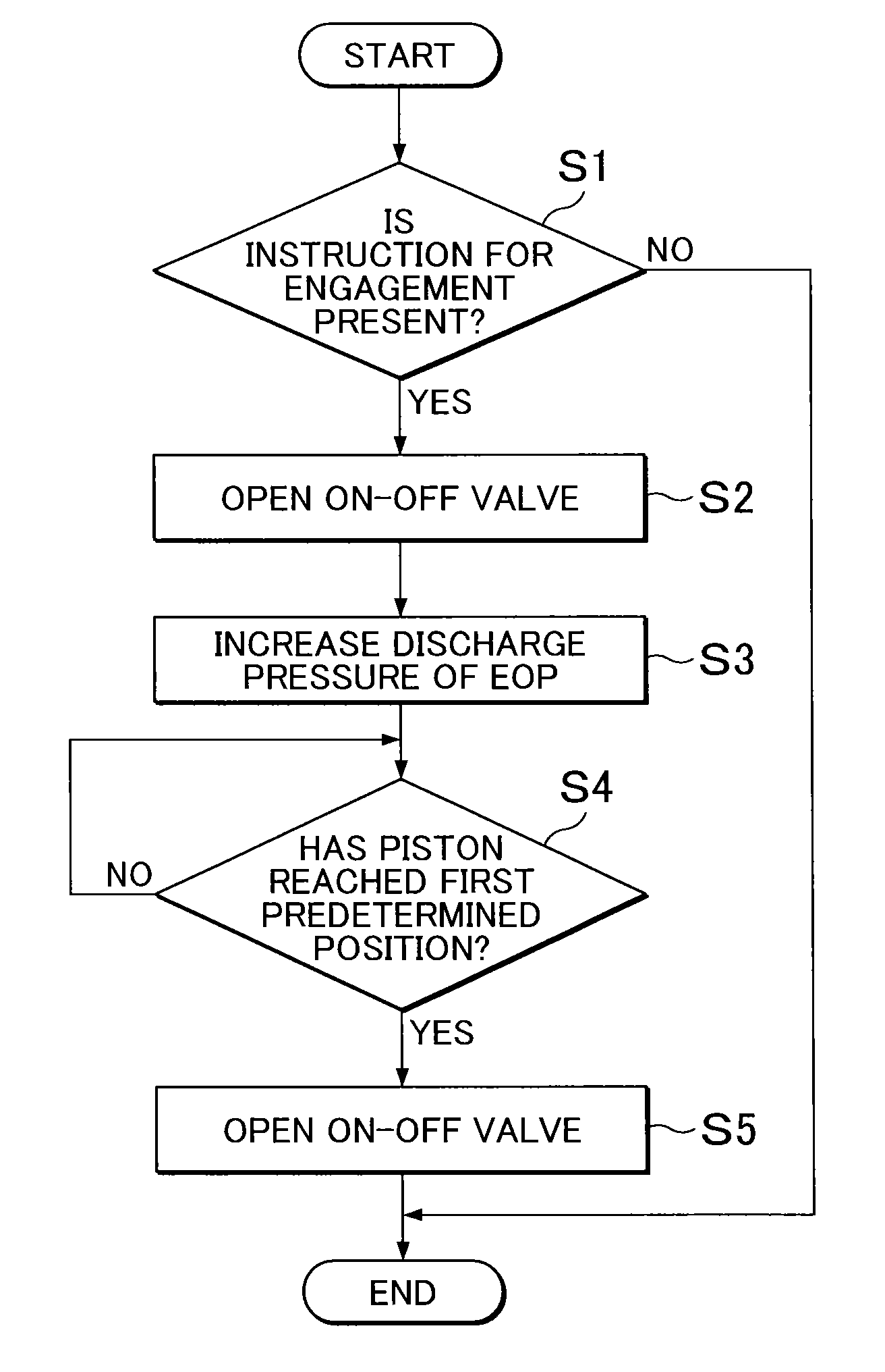
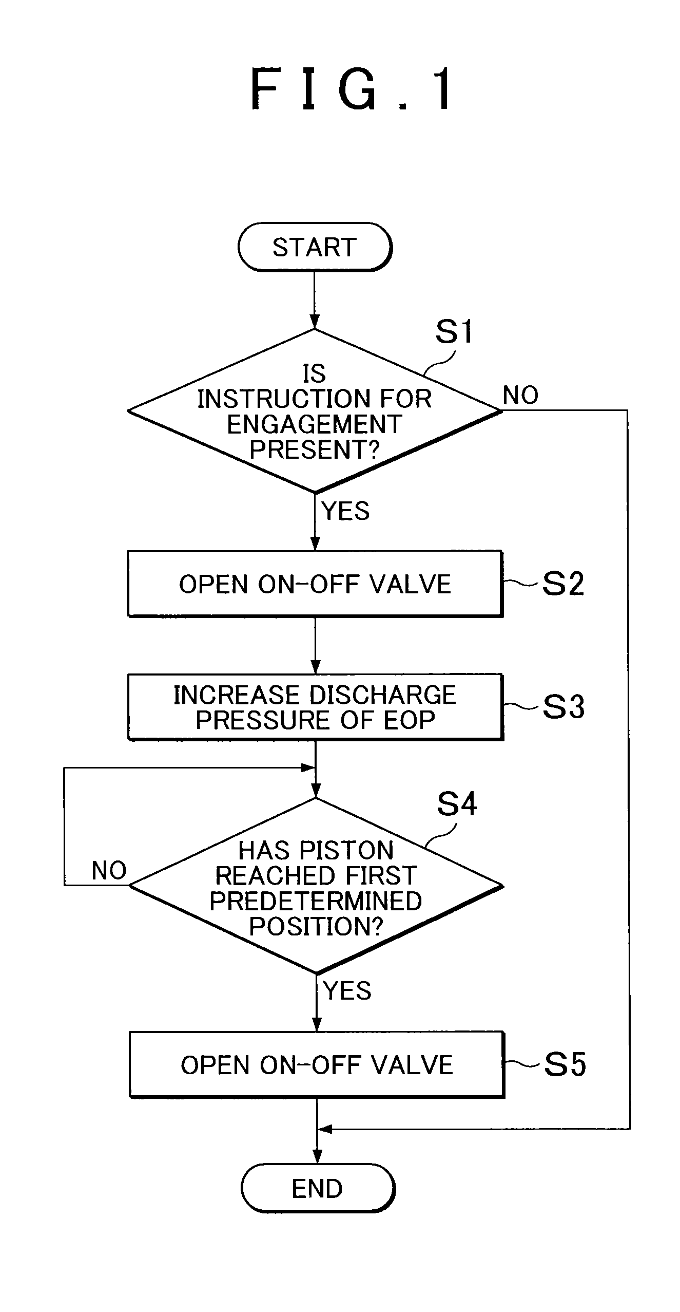
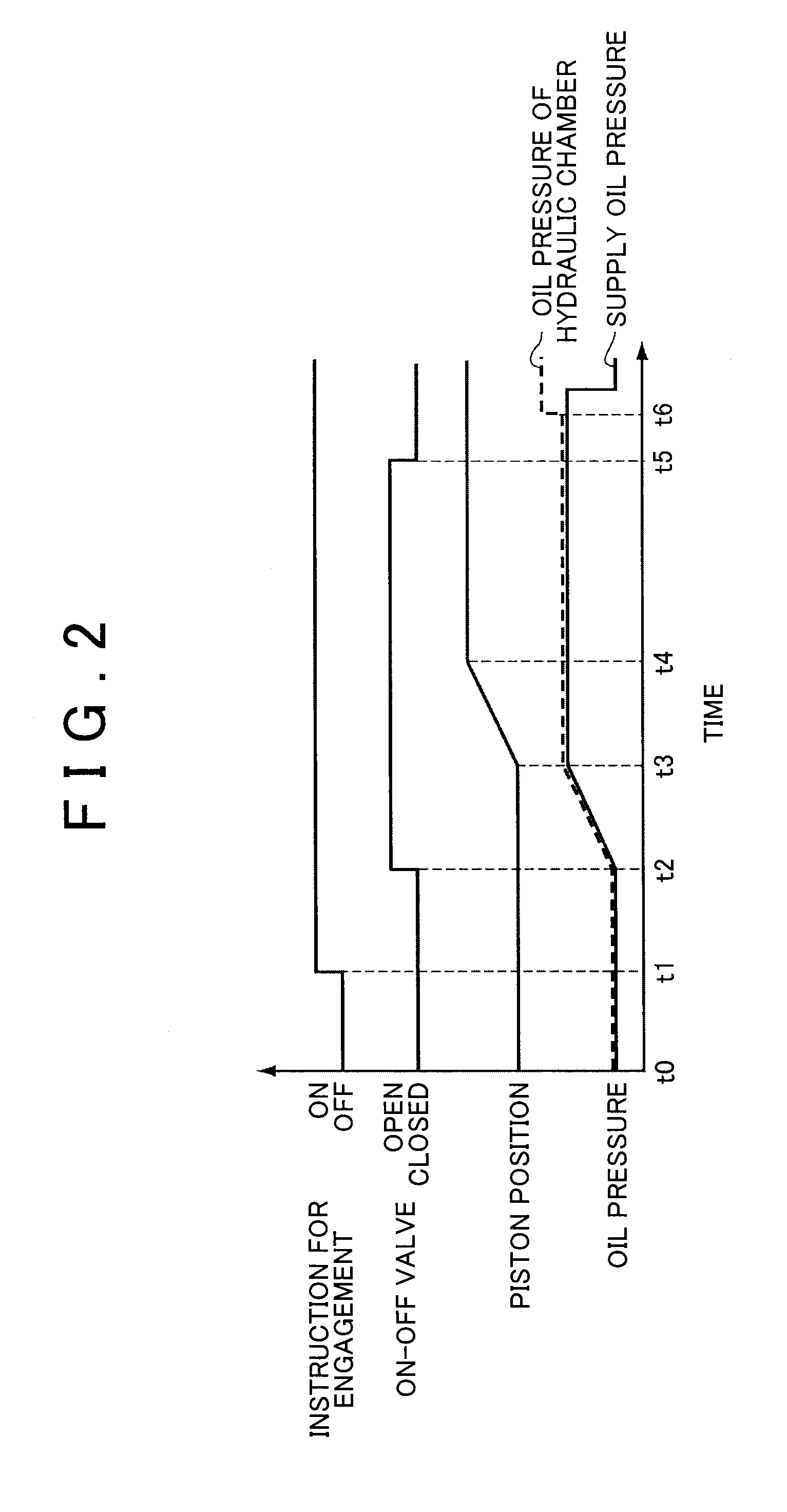
[0025]A meshing type engagement mechanism according to the invention is provided with a first member where first dog teeth are formed and a second member where second dog teeth are formed. The meshing type engagement mechanism according to the invention is configured to allow the first dog teeth and the second dog teeth to mesh with each other when the second member is pressed and moved to the first member side. An example of this meshing type engagement mechanism is illustrated in FIG. 5. A meshing type engagement mechanism 1 that is illustrated in FIG. 5 is mounted in a vehicle. The meshing type engagement mechanism 1 is provided with an input member 2 and an output member 3. A torque is transmitted to the input member 2 from a power source such as an engine (not illustrated). The output member 3 is connected to a drive wheel (not illustrated) or the like. The input member 2 and the output member 3 are rotatably held in a casing (not illustrated) by a bearing or the like. The inpu...


PUM


Abstract

A control system for a meshing type engagement mechanism includes a meshing type engagement mechanism and an electronic control unit. The electronic control unit is configured to allow a fluid chamber to be filled with a fluid by putting a switching valve into a cut-off state after respective dog teeth mesh with each other by a second member reaching a predetermined position determined in advance in response to a fluid pressure of the fluid chamber such that the second member is pressed in the direction in which the second member is separated from a first member by a release force depending on the torque transmitted between a surface of a first tooth and a surface of a second tooth, the fluid pressure of the fluid chamber is increased, and an engagement state between the first member and the second member is maintained by the fluid pressure which is increased.

Description


Claims


Application Information

Patent Timeline
Owner TOYOTA JIDOSHA KK
Learn More