Quantization Method and Apparatus in Encoding/Decoding

a quantitative technology and encoding technology, applied in the field of image encoding, can solve the problems of increasing processing complexity, affecting the and significantly different sequences, so as to improve the subjective quality of encoded pictures and improve encoded efficiency

Active Publication Date: 2016-07-07
HUAWEI TECH CO LTD
View PDF5 Cites 3 Cited by
  • Summary
  • Abstract
  • Description
  • Claims
  • Application Information

AI Technical Summary

Benefits of technology

The present invention provides a method and apparatus for quantization in encoding and decoding. This method can achieve quantization by writing a few parameters in the bitstream, which improves efficiency and guarantees subjective quality of the encoded picture. The encoding efficiency is improved because a few bits are saved, while the subjective quality of the encoded picture is improved.

Problems solved by technology

However, picture contents in a sequence are not always the same, rather, variations and details of each picture in a picture sequence are significantly different from each other.
As a result, applying a single quantization matrix to all the pictures in the sequence cannot achieve the best subjective picture quality for the encoded pictures.
It can be seen from the above quantization processes of the individual encoding method that, during the practical application, it is necessary to adjust a value corresponding to each frequency component in the quantization matrix so as to control the image quality, which increases the processing complexity.
On the other hand, an overhead is caused when transferring the corresponding matrix coefficients, which affects the image encoding efficiency and transferring performance.

Method used


Image

  • Quantization Method and Apparatus in Encoding/Decoding
  • Quantization Method and Apparatus in Encoding/Decoding
  • Quantization Method and Apparatus in Encoding/Decoding

Examples


example 1

FOR THE MODEL OF PARAMETERIZED QUANTIZATION

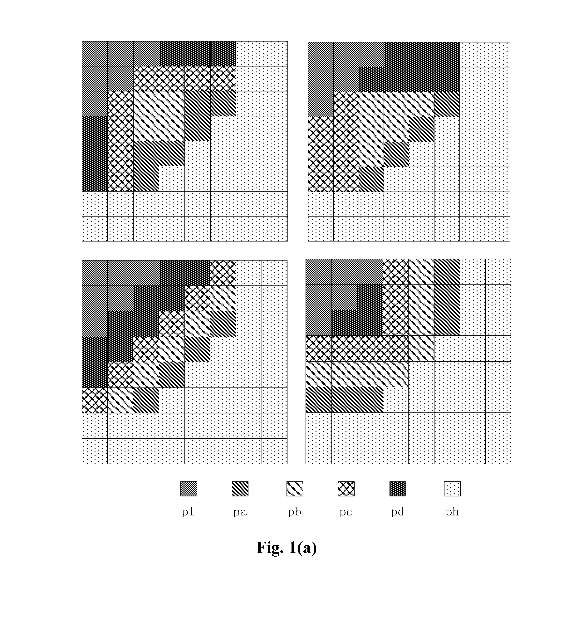
[0087]FIG. 1(a) shows an example model of parameterized quantization with matrices size of 8×8, 6 band parameters (q_para[i], i=1, . . . , 6) and 4 band distribution parameters (q_mode=0, . . . , 3).

[0088]In other words, in FIG. 1(a), 6 parameters (p1, pa, pb, pc, pd, ph) are assigned to represent 6 frequency bands. The positions of the parameters (p1, pa, pb, pc, pd, ph) in each of the 8×8 matrices are different and correspond to one type of frequency band distribution model. The distribution model is designated with the band distribution parameter q_mode.

[0089]For example, FIG. 1(a) lists 4 sorts of frequency band distribution model, that is, the band distribution parameter can have a value of 0, 1, 2 or 3.

[0090]Hence, the corresponding quantization model is expressed as:

WQx, y[i]=(q_mode, q_para[i]) i=1 . . . 6, x, y=0 . . . 7;

or,

WQx, y[i]=(q_para[i], q_mode) i=1 . . . 6, x, y=0 . . . 7.

Where, WQ represents a weighting quantization param...

example 2

FOR THE MODEL OF PARAMETERIZED QUANTIZATION

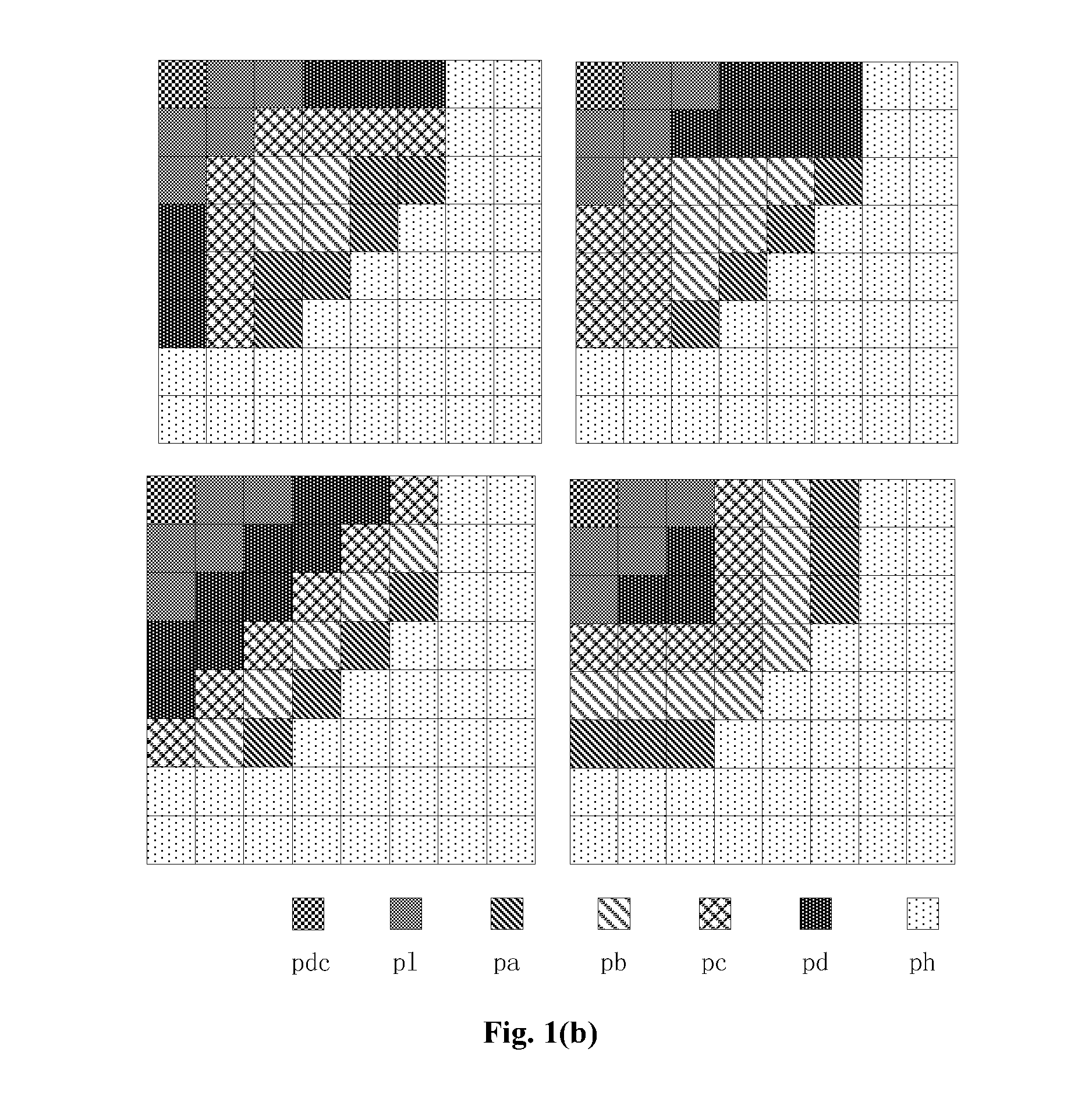
[0091]FIG. 1(b) shows an example model of parameterized quantization with 8×8 matrices, 7 band parameters (q_para[i], i=1, . . . , 7) and 4 band distribution parameters.

[0092]In other words, FIG. 1(b) shows an example of distribution configurations with 7 frequency band parameters, where 7 parameters (pdc, p1, pa, pb, pc, pd, ph) represent 7 frequency bands. In this case, the corresponding parameterized quantization models are expressed as:

WQx, y[i]=(q_mode, q_para[i]) i=1 . . . 7, x, y=0 . . . 7;

or,

WQx, y[i]=(q_para[i], q_mode) i=1 . . . 7 , x, y=0 . . . 7.

[0093]Thus, a parameterized quantization model with n band parameters can be expressed as:

WQx, y[i]=(q_mode, q_para[i]), i=1 . . . n, x=0 . . . M-1, y=0 . . . N-1   (2)

or,

WQx, y[i]=(q_para[i], q_mode) i=1 . . . n, x=0 . . . M-1, y=0 . . . N-1   (3)

[0094]where n<M×N (M,N=2, 4, 8, 16 or other size, M, N are the sizes of the transformed coefficient matrix or quantization matrix).

EXAMPLE 3 F...

embodiment 1

coding / Decoding According To A Quantization Parameter Model

At The Encoding End:

[0104]It is assumed that the model of parameterized quantization is expressed by Equation (2), according to the 6-parameter model shown in FIG. (1a) and assuming that the header of the encoding unit is a picture header, the processing at the encoding end specifically includes the following steps:

[0105](1) The frequency band weighting coefficients are computed by using the model parameter (q_mode, q_para[i]) i=1 . . . 6. Assuming the weighting value threshold T equals to 10, hence a positive weighting is set when q_para[i] is greater than T, and a negative weighting is set when it is smaller than T.

[0106]For example, the 6-parameter weighting quantization model for the distribution configuration that q_mode equals to 0 is:

(q_mode=0, q_para[1˜6])=(0, 0, 3, 2, 1, 1,−1);

[0107]the band parameters are: q_para[1˜6]=(10, 13, 12, 11, 11, 9).

[0108](2) A new quantization matrix is computed by using the weighting coe...


PUM


Abstract

A method and apparatus is provided for encoding / decoding an image in a process of transmission. A plurality of frequency bands are divided into different frequency zones; a scaling value is assigned for each frequency zone; a scaling matrix is established with coefficients comprising the scaling values for the different frequency zones; wherein a number of the frequency zones is smaller than a number of coefficients in the matrix, and each frequency zone corresponds to one scaling value in the coefficient matrix such that every coefficient in said each frequency zone has the same scaling value that is assigned to said frequency bands; and corresponding quantization / dequantization is performed in process of encoding / decoding respectively using the scaling matrix,

Description

CROSS-REFERENCE TO RELATED APPLICATION[0001]This application is a divisional application of U.S. patent application Ser. No. 12 / 210,890, filed Sep. 15, 2008, which is a continuation of International Patent Application No. PCT / CN2007 / 000862, filed Mar. 16, 2007, which claims priority to Chinese Patent Application No. 200610064857.5, filed Mar. 16, 2006, each of which is hereby incorporated by reference in its entirety.FIELD OF THE INVENTION[0002]The present invention relates to image encoding, and in particular, to quantization technology in encoding / decoding.BACKGROUND OF THE INVENTION[0003]In imaging encoding technology, transformed coefficients are quantized by using a quantization matrix. The quantized result is then subjected to entropy encoding to produce a compressed bitstream. The quality of the encoded image can be controlled by adjusting the coefficients in the quantization matrix.[0004]The image may include a stationary picture, a frame of moving pictures, a residual pictu...

Claims


Application Information

Patent Timeline
Patent Type & Authority Applications(United States)
IPC IPC(8): H04N19/174H04N19/176H04N19/70H04N19/18H04N19/46H04N19/61H04N19/126H04N19/177
CPCH04N19/174H04N19/126H04N19/176H04N19/70H04N19/18H04N19/46H04N19/61H04N19/177H04N19/154
Inventor ZHENG, JIANHUACHEN, JIANWENHE, YUNMENG, XINJIAN
Owner HUAWEI TECH CO LTD
Why Eureka
Try Eureka