
Novel fluid treatment systems and methods

a technology of fluid treatment system and fluid treatment method, which is applied in the direction of water treatment multi-stage treatment, water treatment water treatment, water treatment water from quaries, etc., can solve the problems of high energy consumption, impracticality of wastewater remediation from conventional hydrodynamic solutions, and exorbitant cos

Active Publication Date: 2016-06-30
BURST ENERGIES INC
View PDF3 Cites 7 Cited by
  • Summary
  • Abstract
  • Description
  • Claims
  • Application Information

AI Technical Summary

Benefits of technology

The present invention provides a fluid treatment system that uses multi-stage cavitation to increase the amount of active cavitation in a fluid. This is achieved by a multi-stage cavitation subassembly that includes a first cavitation-inducing feature for cavitating the fluid, a second cavitation-inducing feature for further cavitating the fluid, and a velocity-imparting component that imparts the fluid with sufficient velocity after it has undergone cavitation in the first feature. The velocity-imparting component can be a rotating impeller or a rotating vane. The system also includes a flow-guiding feature that guides the fluid from the first to the second cavitation-inducing feature. The multi-stage cavitation subassembly can be housed in a housing and includes one or more ultrasonic drivers to facilitate acoustic cavitation within the fluid. The technical effects of the invention include increased fluid treatment efficiency and improved fluid quality.

Problems solved by technology

However, movement of large volumes of fluid at the requisite speed through each of these constrictions to effect hydrodynamic cavitation requires an extremely large energy input.
As a result, achieving wastewater remediation from conventional hydrodynamic solutions remains impractical and exorbitantly expensive.

Method used


Image

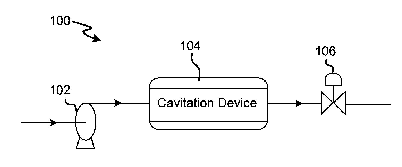
  • Novel fluid treatment systems and methods
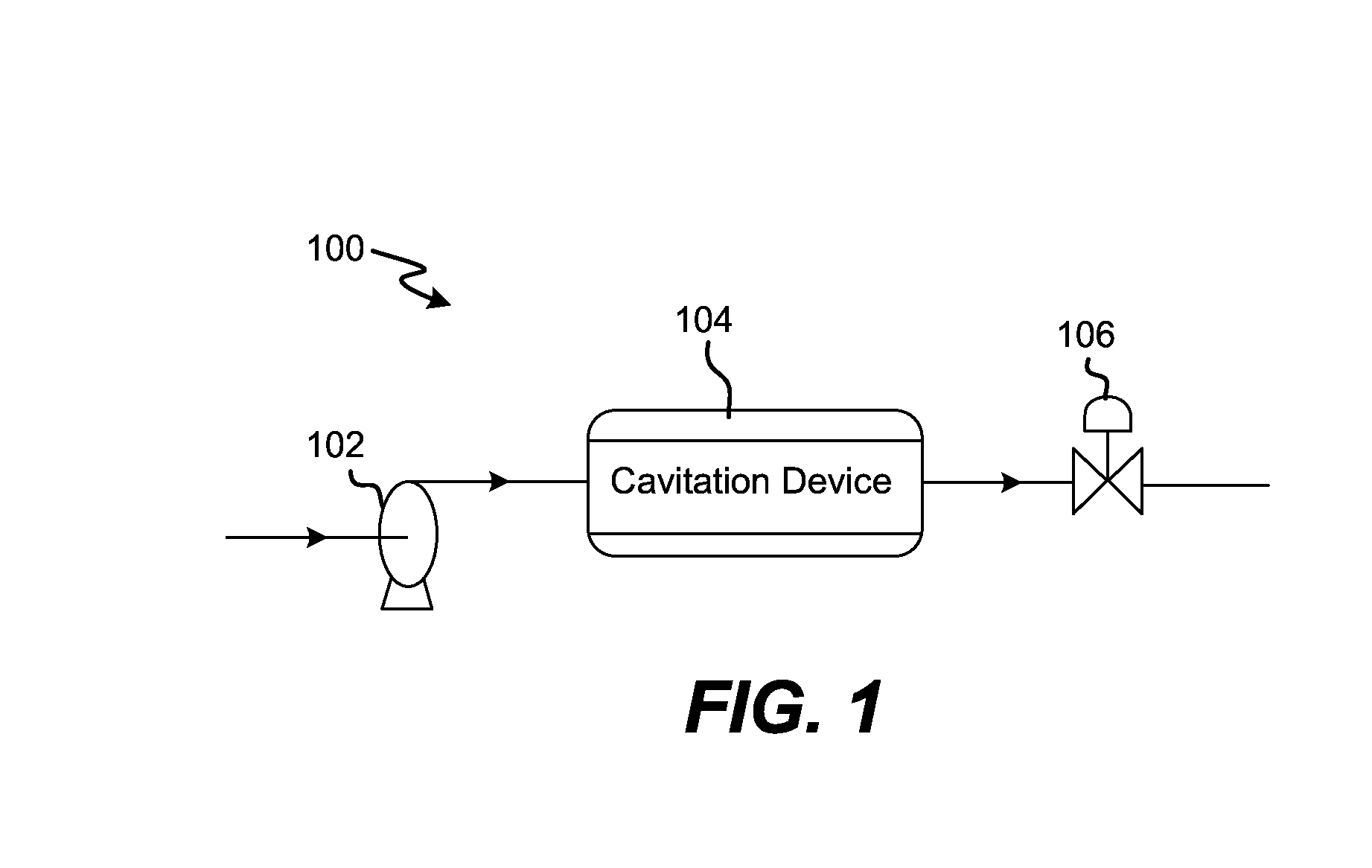
  • Novel fluid treatment systems and methods
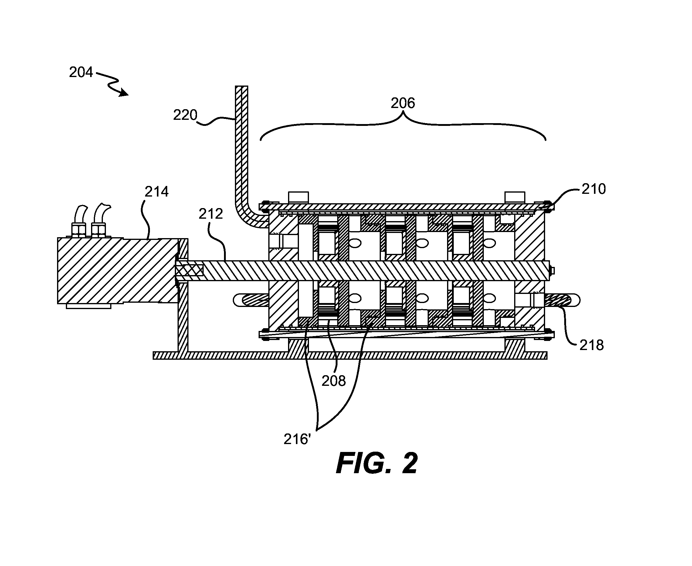
  • Novel fluid treatment systems and methods

Examples


Embodiment Construction

[0045]In the following description, numerous specific details are set forth in order to provide a thorough understanding of the present arrangements and teachings. It will be apparent, however, to one skilled in the art that the present arrangements and teachings may be practiced without limitation to some or all of these specific details. In other instances, well-known process steps have not been described in detail in order to not unnecessarily obscure the primary features of the present arrangements and teachings.

[0046]One embodiment of the present arrangements includes cavitation systems that produce enhanced cavitation by increasing the amount of active cavitation in a given fluid flow due to hydrodynamic conditions in the liquid. Hydrodynamic conditions in the liquid cause the pressure of the flowing liquid to decrease below vapor pressure, causing formation of gas or vapor bubbles. Gas or vapor bubble formations are followed by an increase in pressure, causing the bubbles to ...


PUM

PropertyMeasurementUnit
pressureaaaaaaaaaa
pressureaaaaaaaaaa
velocityaaaaaaaaaa

Abstract

A multi-stage cavitation subassembly is described. The multi-stage cavitation subassembly includes: (i) a first cavitation-inducing feature for cavitating a fluid; (ii) a second cavitation-inducing feature that is located downstream from the first cavitation-inducing feature and is designed to cavitate the fluid after the fluid has undergone cavitation in the first cavitation-inducing feature; and (iii) a velocity-imparting component that, in a state of motion and when in contact with the fluid, imparts the fluid with sufficient velocity after the fluid has undergone cavitation in the first cavitation-inducing feature so that the fluid traverses from the first cavitation-inducing feature to the second cavitation-inducing feature.

Description

RELATED APPLICATION[0001]The application claims priority from U.S. Provisional Application having Ser. No. 61 / 862,959, filed on Aug. 6, 2013, which is incorporated herein by reference for all purposes.FIELD OF THE INVENTION[0002]The present invention relates generally to fluid and solid treatment systems and methods relating thereto. More particularly, the present invention relates to fluid and solid treatment systems and methods using cavitation.BACKGROUND OF THE INVENTION[0003]Cavitation is the formation, growth, and subsequent collapse of gas or vapor bubbles inside a fluid generated by changes in the hydrostatic or hydrodynamic conditions of a fluid. These changes in fluid conditions that lead to cavitation can be caused mechanically (e.g., using ultrasonic waves), optically (e.g., using laser beams), or by bombardment with high-energy particles (e.g., using fast-moving electrons or neutron particles). Regardless of how changes in hydrodynamic conditions are caused, different ty...

Claims


Application Information

Patent Timeline
Patent Type & Authority Applications(United States)
IPC IPC(8): C02F1/36C02F1/28
CPCC02F1/36C02F1/28C02F1/285C02F1/286C02F1/281C02F1/34C02F2301/08C02F2103/008C02F2103/10C02F2303/04C02F2303/06
Inventor MILLER, STEPHEN L.MAHAMUNI, NARESH
Owner BURST ENERGIES INC
Learn More