Snips with One-Hand-Operable Lock Device

a lock device and one-hand technology, applied in the field of pair of snips, can solve the problems of user difficulty in gripping the first and second handles, user's inability to easily lock the shears with one hand,

Inactive Publication Date: 2016-06-30
ALLPROFESSIONAL MFG
View PDF13 Cites 27 Cited by
  • Summary
  • Abstract
  • Description
  • Claims
  • Application Information

AI Technical Summary

Benefits of technology

[0007]The pair of snips is locked and is in a locked position thereof in which the second structural section of the structural member is restrained on the other of the first and second grips and tip ends of the pair of cutting members are prevented from moving away from each other.

Problems solved by technology

However, a user can not lock the shears with one hand easily.
Therefore, it is difficult for the user to grip the first and second handles while moving the lock device counterclockwise to reach and catch the second fastener with one hand.

Method used


Image

  • Snips with One-Hand-Operable Lock Device
  • Snips with One-Hand-Operable Lock Device
  • Snips with One-Hand-Operable Lock Device

Examples


Embodiment Construction

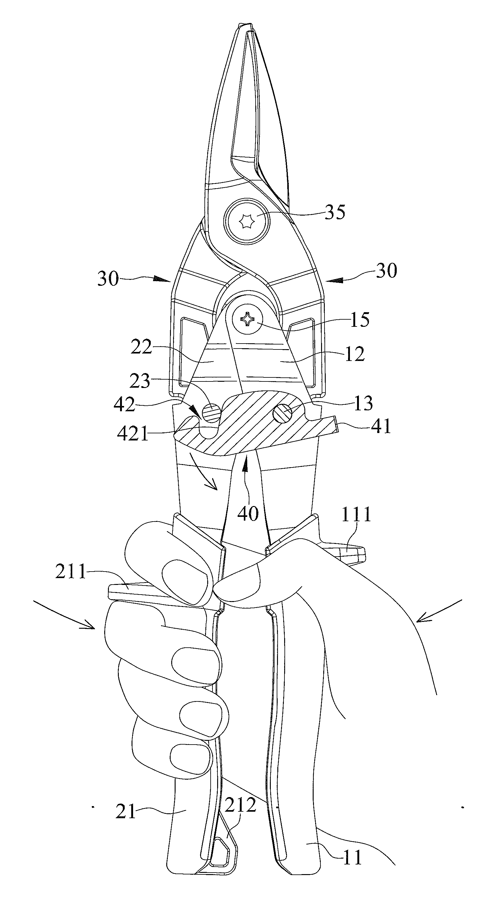
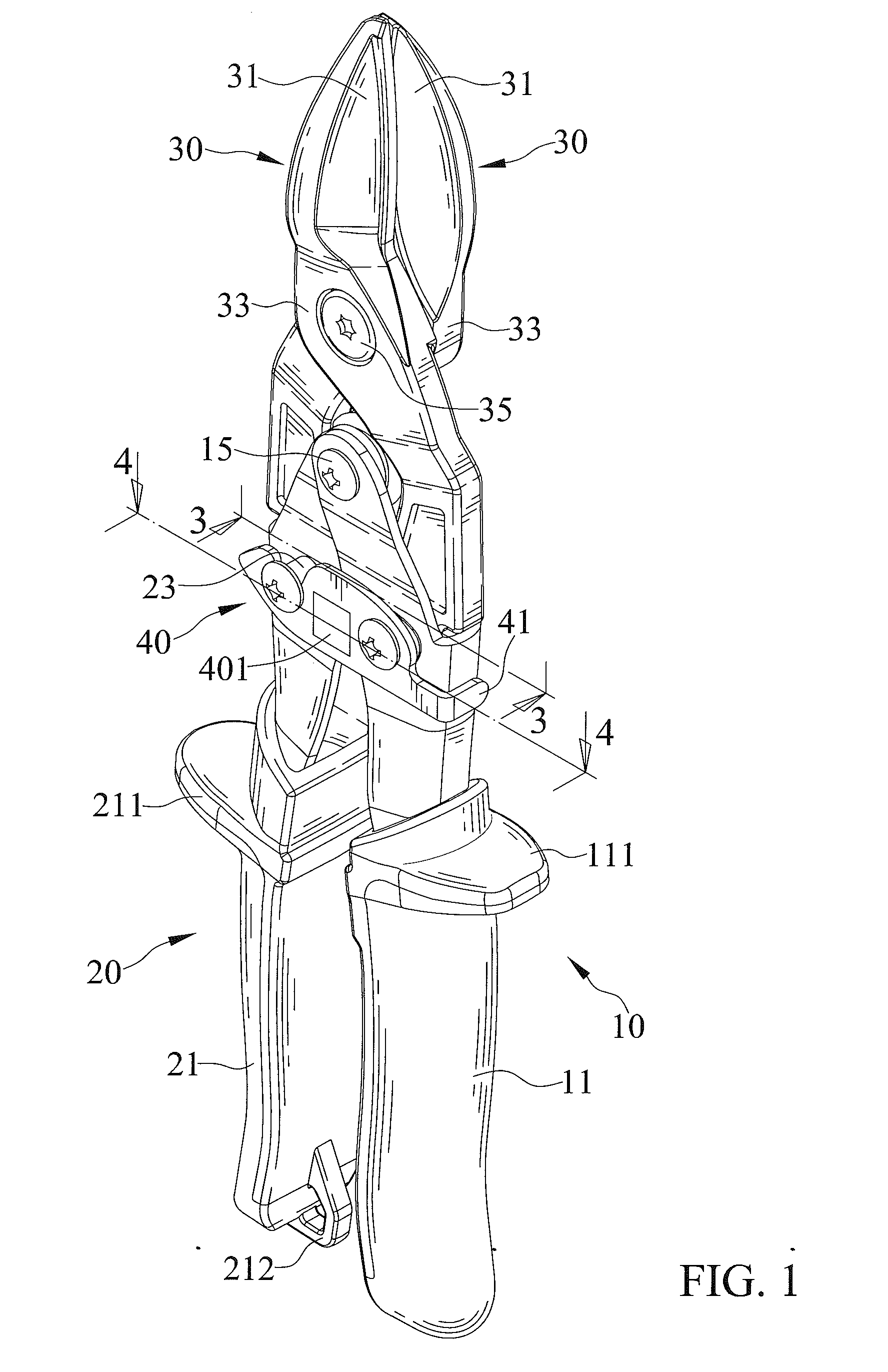
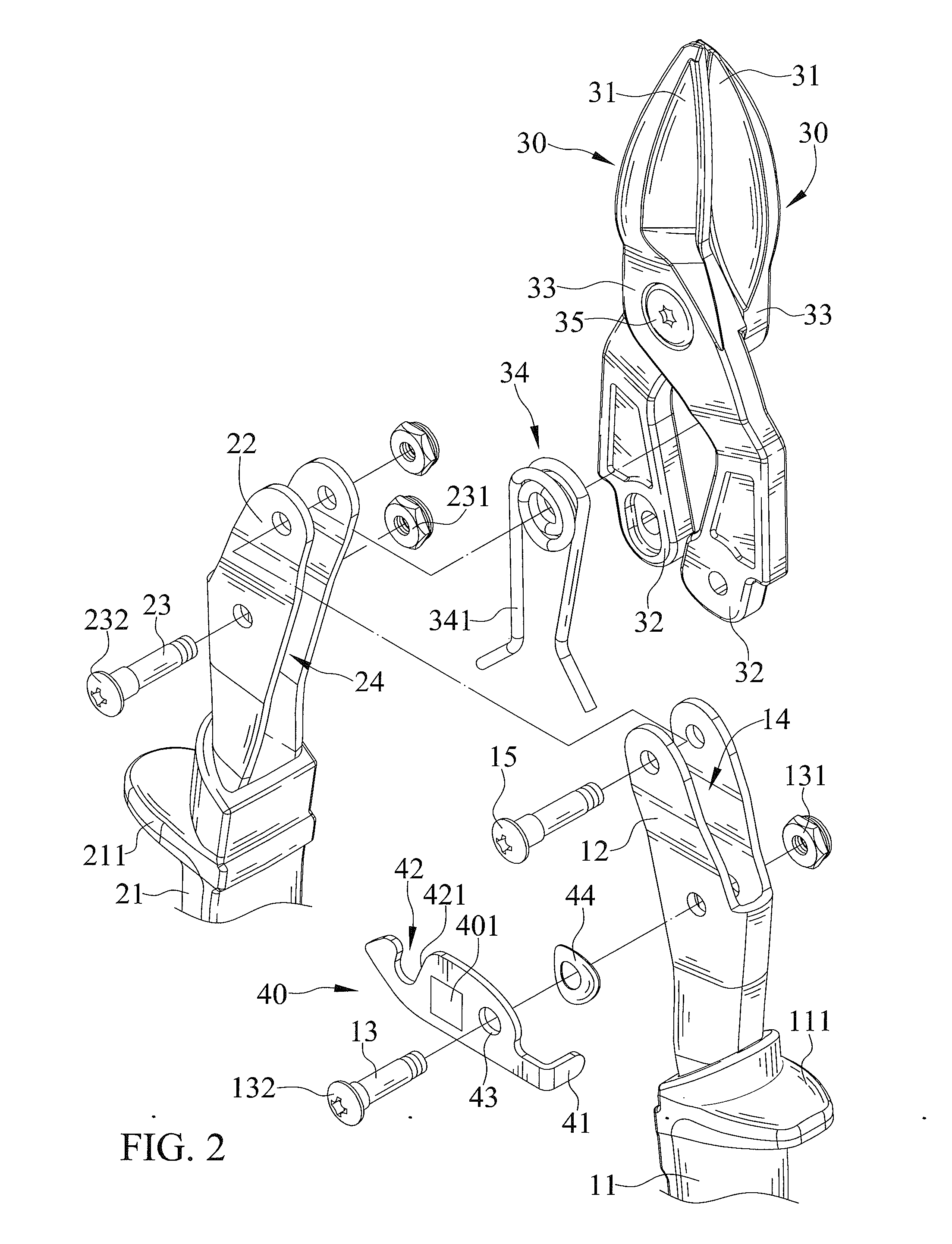
[0022]FIGS. 1 through 7 show a pair of snips with a one-hand-operable lock device in accordance with the present invention. The pair of snips includes a first and second grip 10 and 20, a pair of cutting members 30 and a lock device 40.

[0023]Each of the first and second grips 10 and 20 includes a first end thereof allowing a user to ergonomically grip and a second end thereof connecting to one of the pair of cutting members 30. The first and second snips 10 and 20 are disposed side by side. The first and second grips 10 and 20 are interconnected by a fastener 15. The first and second grips 10 and 20 are pivotal with respect to one another about the fastener 15. Each of the first and second grips 10 and 20 has a body 12 and 22 including two first walls disposed oppositely and in a spaced relationship and a second wall interconnecting and extend between the first walls. The first end of the first grip 10 is sheathed with a first grip cover 11 which further provides for a comfortable g...


PUM


Abstract

A pair of snips with one-hand-operable lock device includes a first and second grip disposed side by side, a pair of cutting members pivotally connecting with each other and including one cutting member connecting to the first grip and the other cutting member connecting to the second grip respectively, and a lock device including a structural member pivotally connecting to the first grip and including a first structural section as a user control end disposed at one of two opposite ends of the structural member, a second structural section as a locking end disposed at the other end of the structural member, and a third structural section disposed between the first and second structural sections and including a pivot extending therefrom and engaging with the first grip.

Description

BACKGROUND OF THE INVENTION[0001]1. Field of the Invention[0002]The present invention relates to a pair of snips and, particularly, to the pair of snips with a lock device which is one-hand-operable.[0003]2. Description of the Related Art[0004]Referring to TW patent No. 1389780, a pair of shears includes a first cutting member, a second cutting member pivotally connecting to the first cutting member about a first pivot, a first handle connecting to the first cutting member, a second handle connecting to the second cutting member and pivotally connecting to the first handle about a second pivot, and a spring supported by the second pivot and including a first leg abutting the first cutting member and a second leg abutting the second cutting member, respectively. Moreover, the pair of shears is adapted to be locked. When the pair of shears is locked, tip ends of the first and second cutting members as well as first and second handles are prevented from moving away from one another. Th...

Claims


Application Information

Patent Timeline
Patent Type & Authority Applications(United States)
IPC IPC(8): B26B13/16
CPCB26B13/16
Inventor HUANG, CHUNG-PING
Owner ALLPROFESSIONAL MFG
Why Eureka
Try Eureka