
Minimizing processing load when solving maximum satisfiability problem

a technology of maximum satisfiability and processing load, applied in the field of minimizing processing load when solving maximum satisfiability problems, to achieve the effect of reducing the processing load of solving the maximum satisfiability problem

Inactive Publication Date: 2016-06-23
IBM CORP
View PDF3 Cites 1 Cited by
  • Summary
  • Abstract
  • Description
  • Claims
  • Application Information

AI Technical Summary

Benefits of technology

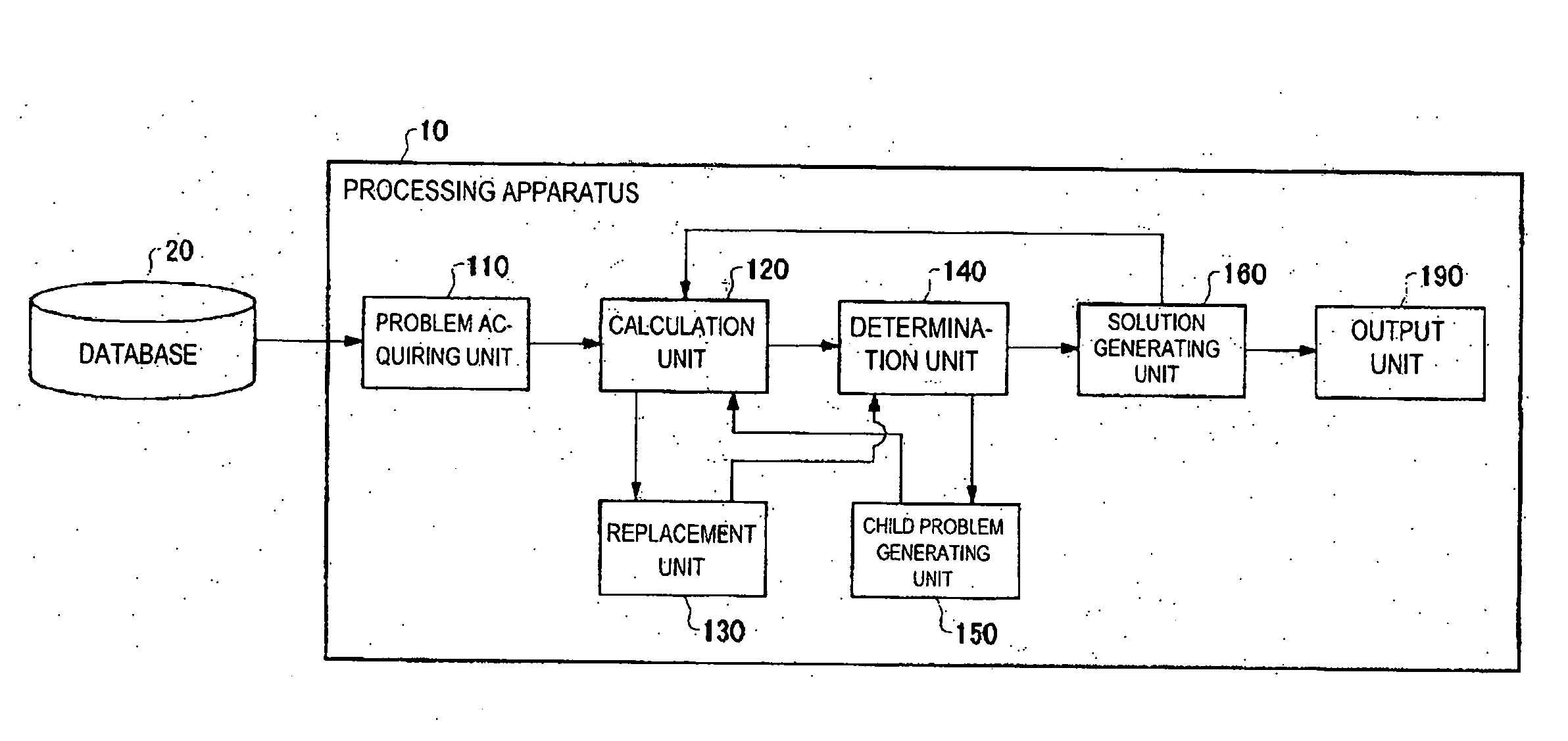
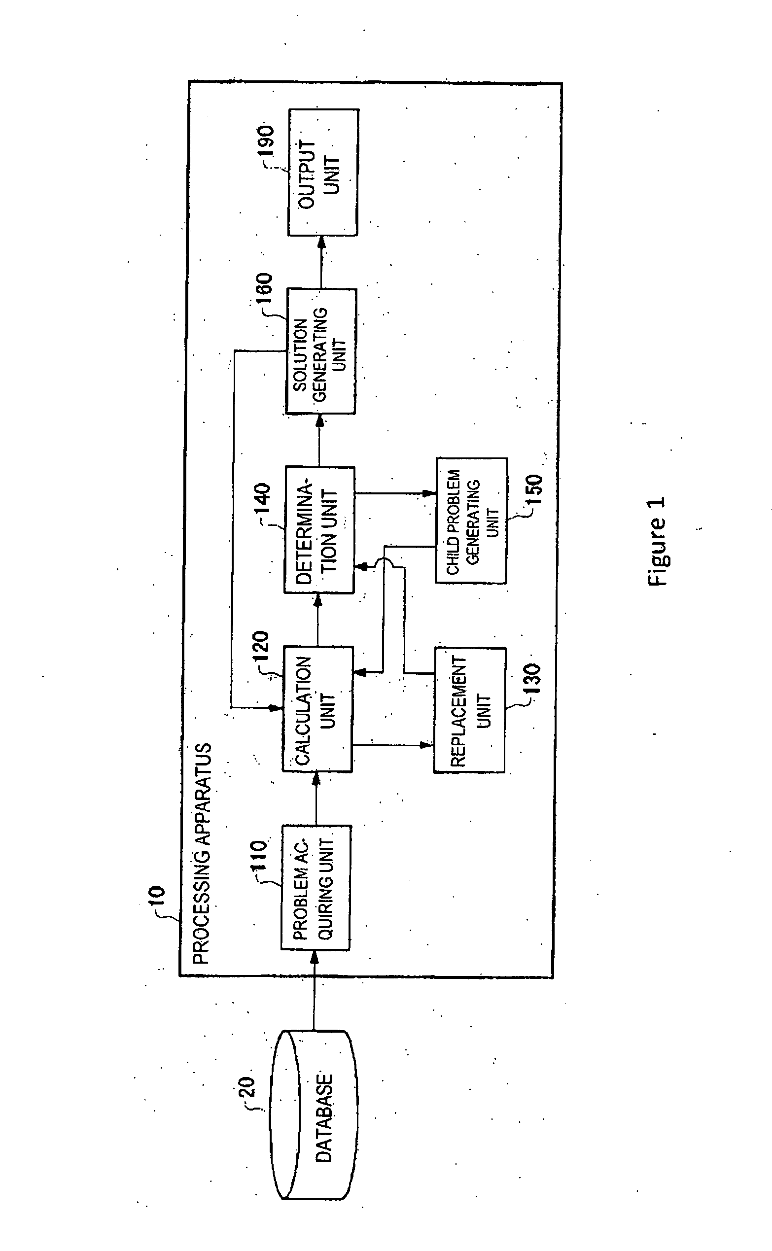
The present invention provides a processing apparatus, method and program for solving a problem of maximizing a sum of weights associated with clauses that each take a predetermined logical value. This apparatus includes a calculation unit for calculating boundary values of the sum of weights in a case where a first logical variable has a predetermined logical relation to a second logical variable, and a replacement unit for replacing the first logical variable in each of the plurality of clauses with a clause formed by using the second logical variable, in a case where the boundary values satisfy a predetermined condition. This invention simplifies the processing load of solving the maximum satisfiability problem and improves efficiency.

Problems solved by technology

Unfortunately, only Inference Rule in which a unique logical value is assigned to each logical variable in the case where a predetermined condition is established is known up to now, and a new simplification technique is necessary to further reduce a processing load of solving the maximum satisfiability problem.

Method used


Image

  • Minimizing processing load when solving maximum satisfiability problem
  • Minimizing processing load when solving maximum satisfiability problem
  • Minimizing processing load when solving maximum satisfiability problem

Examples


Embodiment Construction

[0019]As required, detailed embodiments are disclosed herein; however, it is to be understood that the disclosed embodiments are merely examples and that the systems and methods described below can be embodied in various forms. Therefore, specific structural and functional details disclosed herein are not to be interpreted as limiting, but merely as a basis for the claims and as a representative basis for teaching one skilled in the art to variously employ the present subject matter in virtually any appropriately detailed structure and function. Further, the terms and phrases used herein are not intended to be limiting, but rather, to provide an understandable description of the concepts.

[0020]The description of the present invention has been presented for purposes of illustration and description, but is not intended to be exhaustive or limited to the invention in the form disclosed. Many modifications and variations will be apparent to those of ordinary skill in the art without dep...


PUM


Abstract

Provided is a processing apparatus that processes a problem for minimizing the sum of weights respectively associated with clauses that each become false, of a plurality of clauses each based on at least one logical variable, the processing apparatus including: a calculation unit for calculating a boundary value of the sum of the weights in a case where it is assumed that a first logical variable and a second logical variable have a predetermined logical relation; and a replacement unit for replacing the first logical variable in each of the plurality of clauses with a logical expression formed by using the second logical variable, in a case where the boundary value satisfies a predetermined condition.

Description

CROSS-REFERENCE TO RELATED APPLICATIONS[0001]This application is based upon and claims priority from Japanese Patent Application Number 2014-257219, filed on Dec. 19, 2014, the entire disclosure of each application is incorporated by reference in its entirety.BACKGROUND[0002]A maximum satisfiability problem (MAX SAT) is the problem to find an assignment to logical variables that maximizes the weight sum of a plurality of satisfied logical expressions (clauses) including a plurality of logical variables. The MAX SAT can be solved according to a branch-and-bound method including: assigning a logical value to the logical variables to generate child problems; and recursively solving the child problems.[0003]Unfortunately, as the size of a problem becomes larger, the number of child problems generated by the branch-and-bound method exponentially increases, and hence a larger amount of processing resource is required to obtain an optimum solution. In view of this, a technique of a simplif...

Claims


Application Information

Patent Timeline
IPC IPC(8): G06F7/544
CPCG06F7/5443G06F17/11
Inventor SHIRAGA, TAKEHARUYANAGISAWA, HIROKI
Owner IBM CORP
Learn More