
Transport device for conveying products

a technology for transporting devices and products, applied in mechanical conveyors, packaging, fastening devices, etc., can solve problems such as the inability to reliably retain products

Active Publication Date: 2016-06-23
UHLMANN PAC SYST
View PDF12 Cites 29 Cited by
  • Summary
  • Abstract
  • Description
  • Claims
  • Application Information

AI Technical Summary

Benefits of technology

The present disclosure describes a transport device that can reliably transport products along different paths with varying conveying directions. The device is made up of a connecting element (such as a connecting rod) and retaining elements that guide the products along the connecting rod. The retaining elements are arranged on the sides of slides that face each other, allowing for the closest proximity when holding narrow products, and can be adjusted continuously to accommodate products with different dimensions or widths. This transport device eliminates the need for predefined formats or manual adjustments when conveying different products.

Problems solved by technology

As a result, the product is no longer retained reliably

Method used


Image

  • Transport device for conveying products
  • Transport device for conveying products
  • Transport device for conveying products

Examples


first embodiment

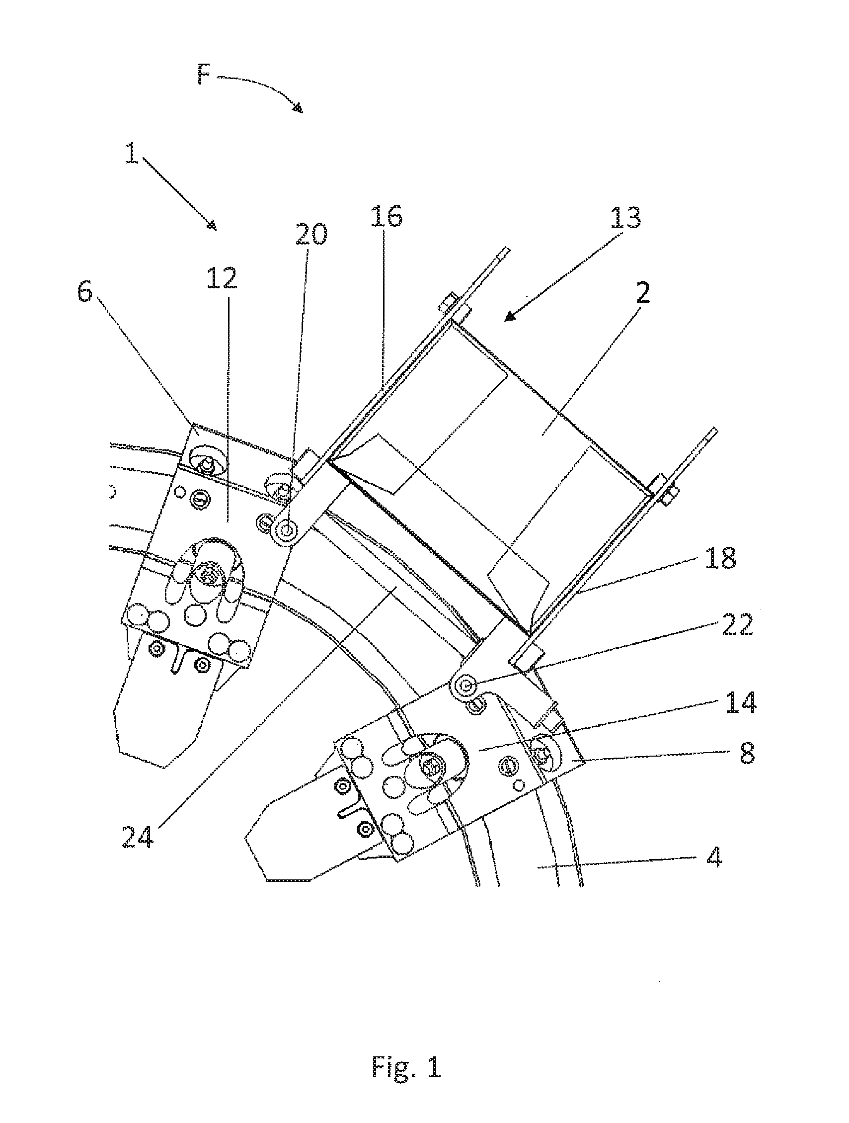
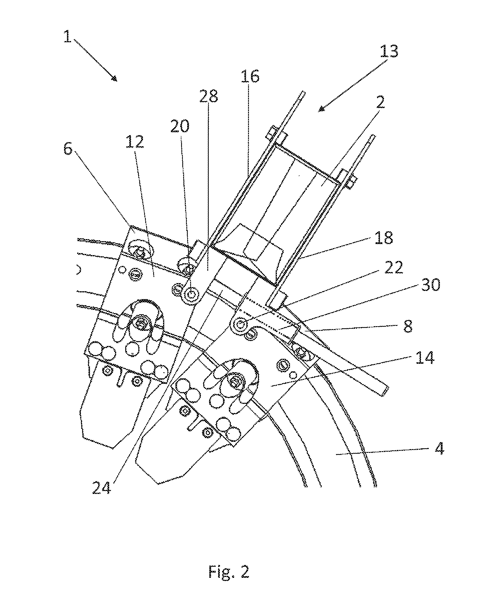
[0025]FIG. 1 shows a side view of the structure of a transport device 1 according to the present disclosure for conveying products 2, especially folding boxes. The transport device 1 comprises a stationary, endless guide rail 4 for guiding at least one pair of movable slides, i.e., a first slide 6 and a second slide 8, in a variable conveying direction F. The conveying direction F can also be opposite to the one shown. The slides serve to convey the products 2 and are moved along the guide rail 4. Even though only one pair of slides 6, 8 is shown in FIG. 1, usually several pairs of slides 6, 8 will be moving simultaneously along the same guide rail 4. Within the pair, either the first slide 6 or the second slide 8 can be in the leading position with respect to the conveying direction F.

[0026]FIG. 1 shows only a part, namely, a curved section, of the endless guide rail 4. The first and second slides 6, 8 move along the outer side of the guide rail 4 in the clockwise or counterclockwi...

second embodiment

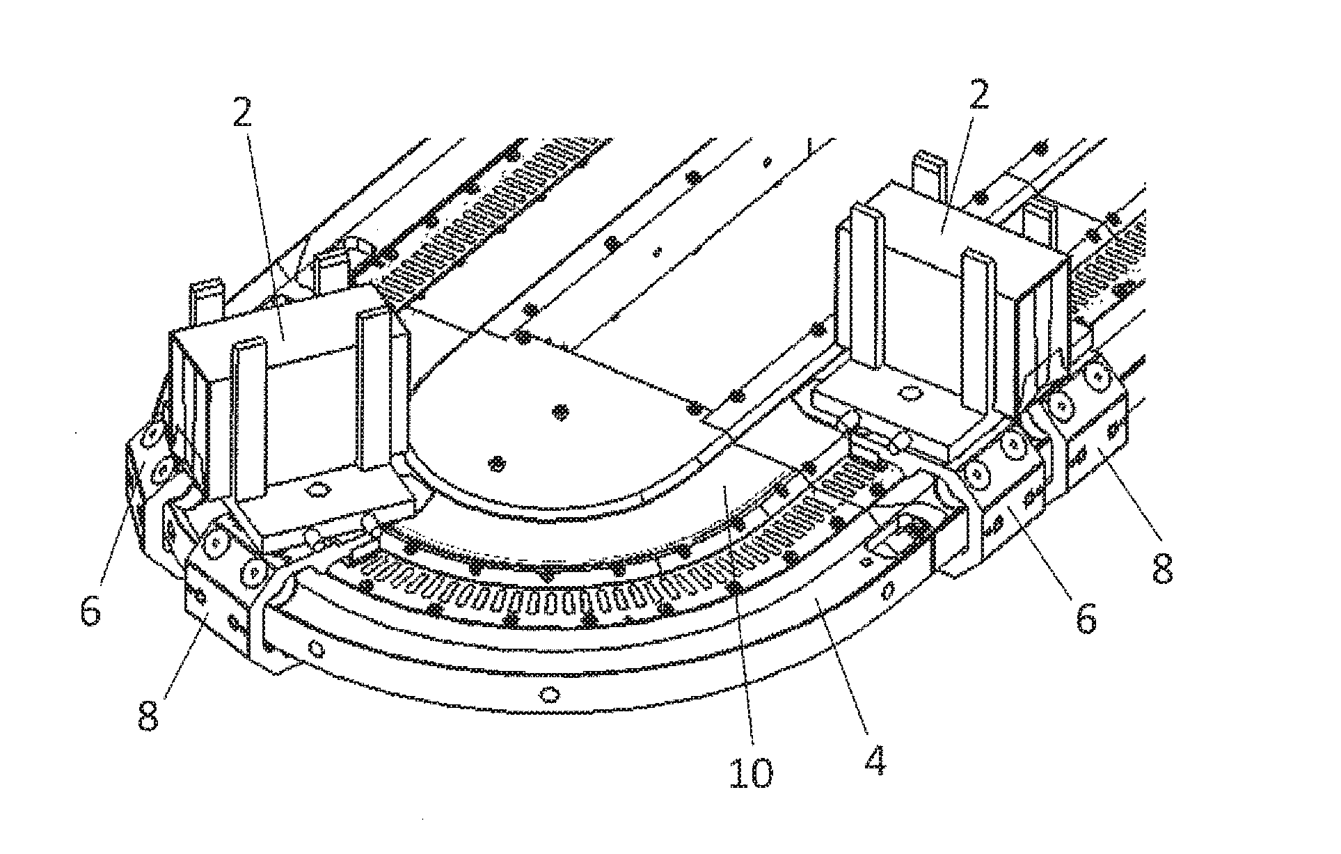
[0041]FIGS. 5 and 6 show perspective views of the structure of the transport device 1 according to the present disclosure for conveying products 2, especially folding boxes. Essential parts of the embodiment of FIGS. 5 and 6 are identical to the embodiment of FIGS. 1-4, wherein the same reference numbers designate the same parts, so that there is no need to repeat the description of the identical parts.

[0042]In contrast to FIGS. 1-4, in which the guide rail 4 was arranged in a vertical plane, FIGS. 5 and 6 show a transport device 1 in which the guide rail 4 is arranged in a horizontal plane. The section of the guide rail 4 shown in FIG. 5 is part of a guide rail arrangement with an overall oval shape with two straight rail sections and two curved rail sections.

[0043]A retaining element 16, 18 is provided on each of the two slides 6, 8, in particular on the base bodies 12, 14 of the slides 6, 8. The first and second retaining elements 16, 18 are substantially parallel to each other, ...


PUM


Abstract

The transport device for conveying products comprises at least one pair of movable slides and an endless guide rail for guiding the at least one pair of slides, one behind the other, in a variable conveying direction. A linear motor drive device serves to drive the at least one pair of slides. A retaining element is provided on each of the two slides, wherein the retaining elements of the first slide and of the second slide form a product receiving space between them. The retaining elements on the first and second slides are each rotatably supported around a rotational axis, which is substantially perpendicular to the variable conveying direction. At least one connecting element is provided to connect the retaining elements of the first and second slides together in such a way that the relative orientation of the retaining elements to each other is determined.

Description

RELATED APPLICATIONS[0001]The present patent document claims the benefit of and priority to European Patent Application No. EP 14198627.3 filed Dec. 17, 2014, the entire contents of which are incorporated herein by reference.FIELD AND BACKGROUND[0002]The present disclosure relates to a transport device for conveying products.[0003]In one example of a known transport device for conveying products, several slides are moved along a guide rail independently of each other. The guide rail comprises a linear motor drive device for driving the slides, wherein each slide comprises at least one permanent magnet, which interacts with the linear motor drive device. A transport device of this type with a linear motor drive is known from WO 2013 / 156177 A1.[0004]A transport device which uses a guide rail and several slides individually movable along the guide rail is also known from DE 10 2012 210 329 A1. The slides comprise retaining elements projecting from them perpendicularly to the conveying ...

Claims


Application Information

Patent Timeline
Patent Type & Authority Applications(United States)
IPC IPC(8): B65G54/02
CPCB65G54/02B65G35/06B65G2207/08F16B2/12
Inventor AUMANN, THOMASZIEHER, DANIELFOCHLER, FRITZ
Owner UHLMANN PAC SYST
Learn More