
Methods and apparatus for forming a translating multifocal contact lens

a technology of multifocal contact lenses and manufacturing apparatuses, applied in the field of contact lenses, can solve the problems of compromising vision, lenses that cannot provide good vision for both distance and near viewing, and previously known multifocal lenses are limited by known manufacturing apparatuses

Inactive Publication Date: 2016-06-16
JOHNSON & JOHNSON VISION CARE INC
View PDF5 Cites 0 Cited by
  • Summary
  • Abstract
  • Description
  • Claims
  • Application Information

AI Technical Summary

Benefits of technology

The lens design effectively restricts movement between different vision zones, improving comfort and optical efficiency by providing vertical and rotational stability, allowing for smoother transitions between distance, intermediate, and near vision without compromising vision quality.

Problems solved by technology

Previously known multifocal lenses have been limited by known manufacturing apparatus, such as, for example, cast molding, standard lathing or tooling technology, and injection molding technology.
There is little or no translation required with this type of lens however, consequently two images are seen simultaneously, compromising vision.
It is recognized that these lenses do not provide good vision for both distance and near viewing, and are only worn successfully by those who are willing to accept less than optimal vision.
While there are many designs for soft translating contact lenses, soft contact lenses have difficulty translating across the surface of an eye when the visual direction of an eye changes from a straight-ahead gaze, to a downward gaze.
While other designs may have the capability to translate across the surface of an eye when the visual direction of an eye changes from a straight-ahead gaze, to a downward gaze, but are not very efficient at controlling movement of a lens during an eye's translation to a different visual direction.
Another disadvantage of the prior art is discomfort when worn upon an eye.

Method used


Image

  • Methods and apparatus for forming a translating multifocal contact lens
  • Methods and apparatus for forming a translating multifocal contact lens
  • Methods and apparatus for forming a translating multifocal contact lens

Examples


Embodiment Construction

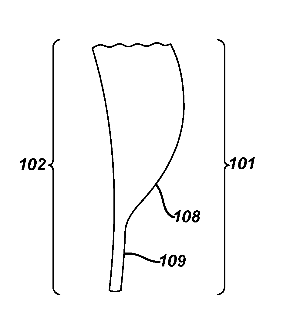
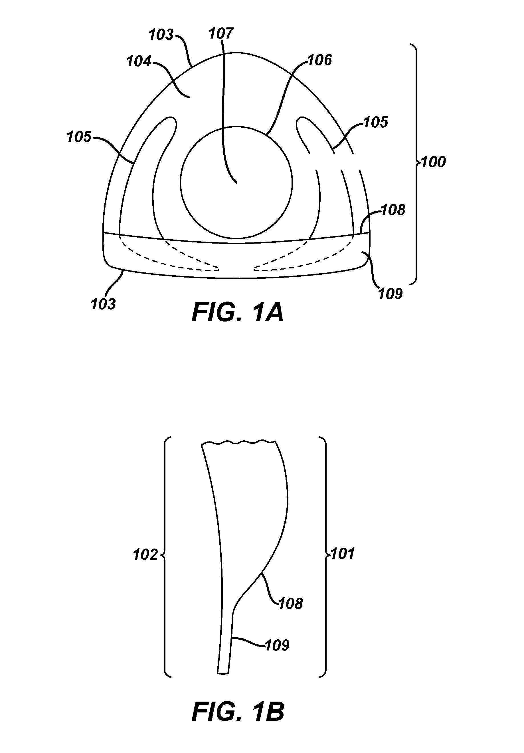
[0018]The present invention provides for a translating multifocal contact lens including one or both of a lower-lid contact surface, and an under-lid support structure, in accordance with a particular patient's eye data and method steps and apparatus for implementing the same. A preferred embodiment of the present invention includes a Free-formed, translating multifocal contact lens, as is discussed more fully below in relation to the various figures.

[0019]In the following sections, detailed descriptions of embodiments of the invention are given. The description of both preferred and alternative embodiments though thorough are exemplary embodiments only, and it is understood to those skilled in the art that variations, modifications and alterations may be apparent. It is therefore to be understood that said exemplary embodiments do not limit the broadness of the aspects of the underlying invention. Method steps described herein are listed in a logical sequence in this discussion. Ho...


PUM

PropertyMeasurementUnit
heightaaaaaaaaaa
widthaaaaaaaaaa
heightaaaaaaaaaa

Abstract

The present invention discloses a translating multifocal contact lens including one or more of multiple Optic Zones, a lower-lid contact surface, and an under-lid support structure and method steps and apparatus for implementing the same. In preferred embodiments, a translating multifocal lens with at least a portion of one surface may be Free-formed comprising one or both of a lower-lid contact surface and an under-lid support structure capable of limiting the amount of translation of a lens across a surface of an eye when an eye changes from one Optic Zone to another.

Description

CROSS REFERENCE TO RELATED APPLICATIONS[0001]This application is a continuation of U.S. application Ser. No. 13 / 854,578, filed on Apr. 1, 2013, which claims priority to the U.S. Provisional Application No. 61 / 617,794 filed Mar. 30, 2012, the contents of which are relied upon and incorporated herein.FIELD OF USE[0002]This invention relates to contact lenses and more specifically, to a translating multifocal contact lens including multiple Optic Zones and one or both of an under-lid support structure and a lower-lid contact structure, wherein the structures aid in limiting lens movement upon an eye when an eye translates between the multiple Optic Zones.BACKGROUND OF THE INVENTION[0003]Bifocal lenses are comprised of two or more areas, or zones, with different optical powers, including typically a far-power Optic Zone for distance vision, and a near-power Optic Zone for near or close up vision. The two zones may be subdivided into additional power zones in which case a lens may be cal...

Claims


Application Information

Patent Timeline
Patent Type & Authority Applications(United States)
IPC IPC(8): G02C7/02G02C7/04
CPCG02C7/027G02C7/048G02C7/043B29D11/00028B29D11/00153B29D11/00961B29D11/00057
Inventor WILDSMITH, CHRISTOPHERWIDMAN, MICHAELADAMS, JONATHAN P.
Owner JOHNSON & JOHNSON VISION CARE INC
Learn More