
Human-interactive type robot system

a robot system and robot technology, applied in the field of human-interactive robot systems, can solve the problems of robots that contact workers, injure workers, and increase the possibility of a worker being endangered, so as to achieve the effect of avoiding the updating of the correction value, reducing the risk to a worker, and raising the safety of the human-interactive robot system

Active Publication Date: 2016-06-16
FANUC LTD
View PDF0 Cites 32 Cited by
  • Summary
  • Abstract
  • Description
  • Claims
  • Application Information

AI Technical Summary

Benefits of technology

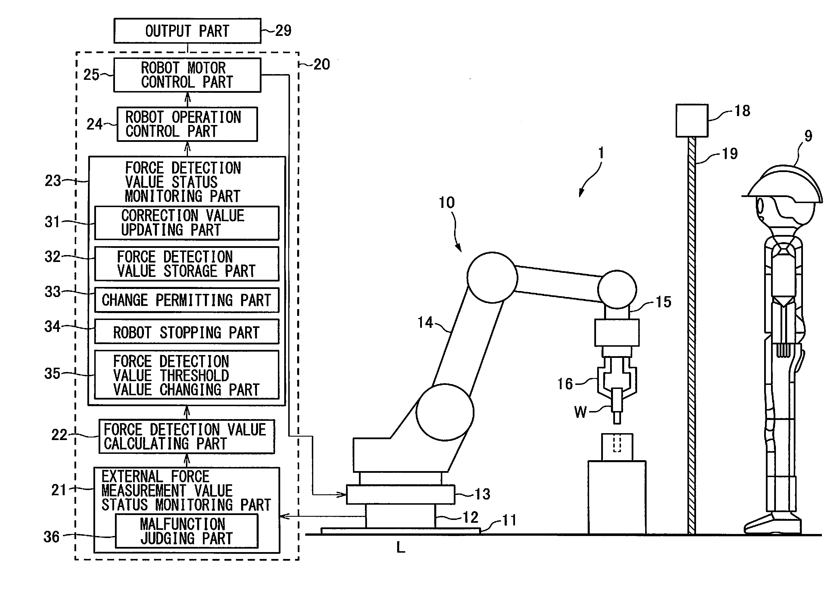
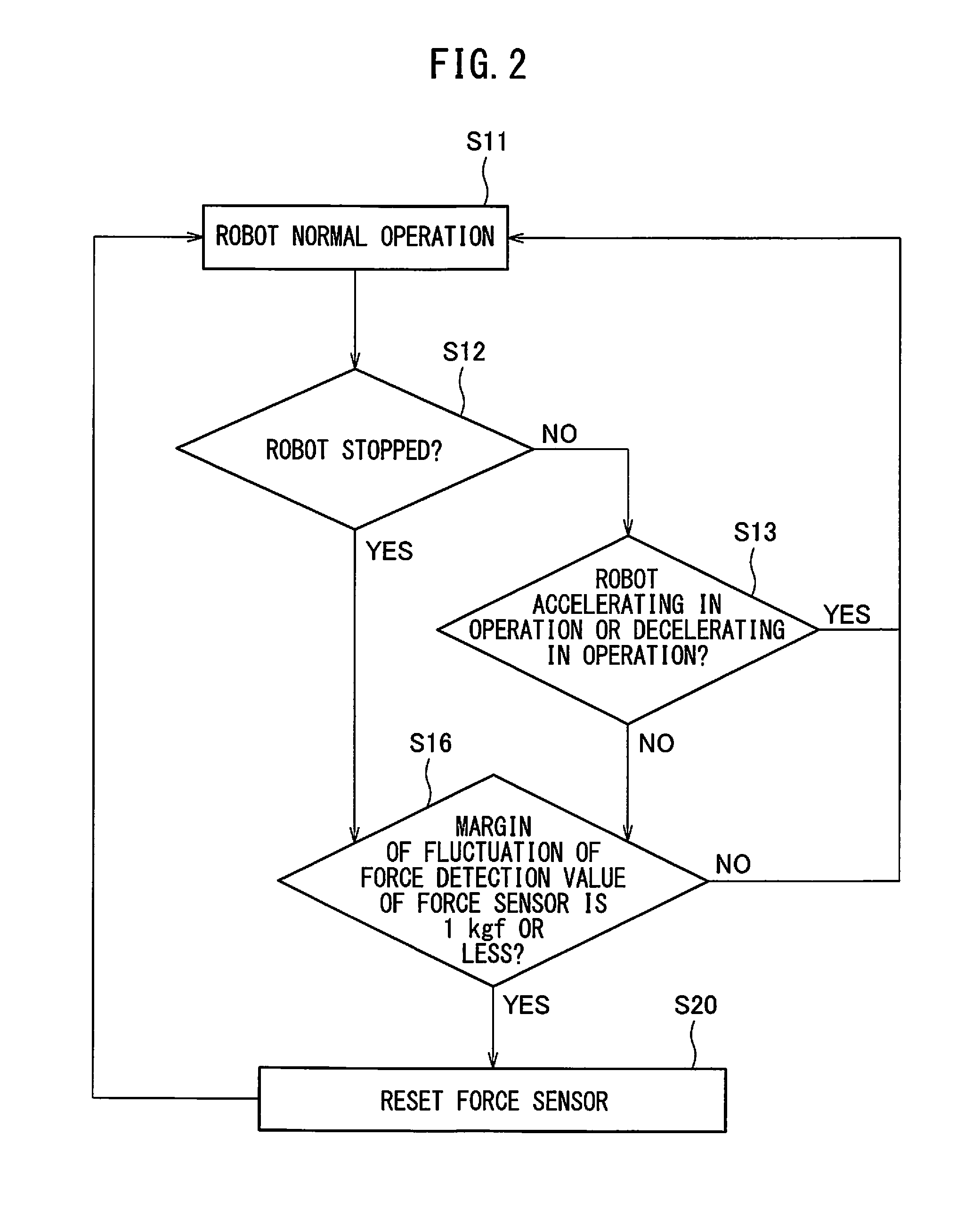
The present invention relates to a human-interactive type robot system, which has a force sensor to detect external force. The invention includes two embodiments. In the first embodiment, the robot system is always operating and the force detection value is always threshold or higher. When this condition is met, the force sensor is reset. This advantageously allows the robot system to quickly and accurately detect and respond to external force, improving work efficiency and safety. In the second embodiment, the force detection value is analyzed to determine if the robot system is operating at a fixed speed or collided with a person or object. When the force detection value is threshold or less, the routine updates the correction value accordingly. This prevents the force sensor from being overwhelmed or unable to detect small contact force. This ensures safe and efficient operation of the robot system. In the third embodiment, the force detection value status monitoring part determines if a predetermined time has elapsed since the previous reset of the force sensor. If a predetermined time has not elapsed, the force sensor is reset. This ensures the force sensor is always kept in a clean state and can quickly detect external force with high precision.

Problems solved by technology

In such a human-interactive type robot, since the worker and robot share the work space, the robot might contact the worker and injure the worker.
If in this way the contact force which the force sensor can recognize becomes larger, there is a greater possibility that a worker will be endangered.

Method used


Image

  • Human-interactive type robot system
  • Human-interactive type robot system
  • Human-interactive type robot system

Examples


first embodiment

[0050]Further, in the first embodiment, the force sensor 12 is never reset in the state where it is acted on by an abnormally large force. Therefore, the measurement value of the force sensor 12 is never excessively corrected. For this reason, a drop in the precision of the force sensor 12 can also be simultaneously prevented.

[0051]In the prior art, the general practice is to update the correction value only when the robot 10 is stopped. As opposed to this, in the first embodiment, when the margin of fluctuation is the fluctuation margin threshold value or less, if the robot 10 is moving by a fixed speed, it is possible to judge that no inertia force due to accelerating or decelerating operation is being received. In such a case, the correction value can be updated. As a result, the correction value can be frequently updated, so the drift of the measurement value of the force sensor 12 can be constantly kept the smallest. Therefore, the precision of the force sensor 12 can be consta...

second embodiment

[0052]FIG. 3 is a flow chart which shows the operation of a human-interactive type robot system based on the present invention. In the flow chart which is shown in FIG. 3, at already explained parts, repeat explanations are omitted for the purpose of avoiding overlap. The same is true for the other later explained flow charts.

[0053]In FIG. 3, instead of step S16 which is shown in FIG. 2, step S16′ is arranged. At step S16′, the force detection value status monitoring part 23 judges if the current force detection value of the force sensor 12 is the force detection value threshold value, for example, 1.5 kgf, or less. Further, when the current force detection value is the force detection value threshold value or less, the routine proceeds to step S20 where the force sensor 12 is reset as explained above.

[0054]The predetermined condition in the second embodiment of the present invention is that the robot 10 be stopped or operating at a fixed speed and the current force detection value ...

third embodiment

[0058]FIG. 4 is a flow chart which shows the operation of a human-interactive type robot system based on the present invention. In FIG. 4, if it is judged at step S11 that the robot 10 is normally operating, the routine proceeds to step S17.

[0059]At step S17, the force detection value status monitoring part 23 judges if a predetermined time, for example, 10 minutes or more, has elapsed from when the force sensor 12 was previously reset. When a predetermined time or more has elapsed from the previous reset, the routine proceeds to step S20 where the force sensor 12 is reset. Note that, when a predetermined time has not elapsed from the time of the previous reset, the routine proceeds to step S12.

[0060]In this connection, the force detection value storage part 32 stores the force detection value when the predetermined condition stands. In the third embodiment, when resetting the force sensor 12, the correction value updating part 31 reads out the stored force detection value from the ...


PUM


Abstract

A human-interactive type robot system which can constantly detect a contact force at a high precision even if the contact force is small, comprising a force sensor which measures a force which the robot receives from the outside and outputs a measurement value, a force detection value calculating part which subtracts a correction value from the measurement value to calculate a force detection value, and a correction value updating part which updates a force detection value when a predetermined condition stands for use as the correction value. The predetermined condition is that the robot is stopped or operating at a fixed speed and a margin of fluctuation of the force detection value at a predetermined unit time is a fluctuation margin threshold value or less or that the robot is stopped and the current force detection value is the force detection value threshold value or less.

Description

BACKGROUND OF THE INVENTION[0001]1. Field of the Invention[0002]The present invention relates to a human-interactive type robot system where a robot and a worker simultaneously share the same work space to perform interactive work.[0003]2. Description of the Related Art[0004]General industrial robots perform work in spaces which are surrounded by safety fences so as to ensure the safety of workers. In recent years, demand has been increasing for human-interactive type robot systems which perform work sharing the same work space as workers.[0005]In work which uses a human-interactive type robot, sometimes the robot and a worker perform separate work in a shared work space and sometimes a worker performs work on a workpiece which is held by the robot. In such a human-interactive type robot, since the worker and robot share the work space, the robot might contact the worker and injure the worker.[0006]For this reason, the contact force between the robot and a worker is detected by a fo...

Claims


Application Information

Patent Timeline
Patent Type & Authority Applications(United States)
IPC IPC(8): B25J9/16
CPCB25J9/1676Y10S901/09B25J9/1694B25J9/1697G05B2219/40202
Inventor NAKAYAMA, KAZUTAKASATO, TAKASHI
Owner FANUC LTD
Learn More