
Lower extremity receiving device for providing enhanced leg mobility during lower body exercise

a receiving device and lower extremity technology, applied in the field of lower body exercise devices, can solve the problems of slipping up the leg, affecting exercise, and preventing optimal gluteal exercise, and achieve the effects of enhancing leg mobility, reducing injury, and reducing injury

Inactive Publication Date: 2016-06-16
KAMINS PAUL
View PDF0 Cites 4 Cited by
  • Summary
  • Abstract
  • Description
  • Claims
  • Application Information

AI Technical Summary

Benefits of technology

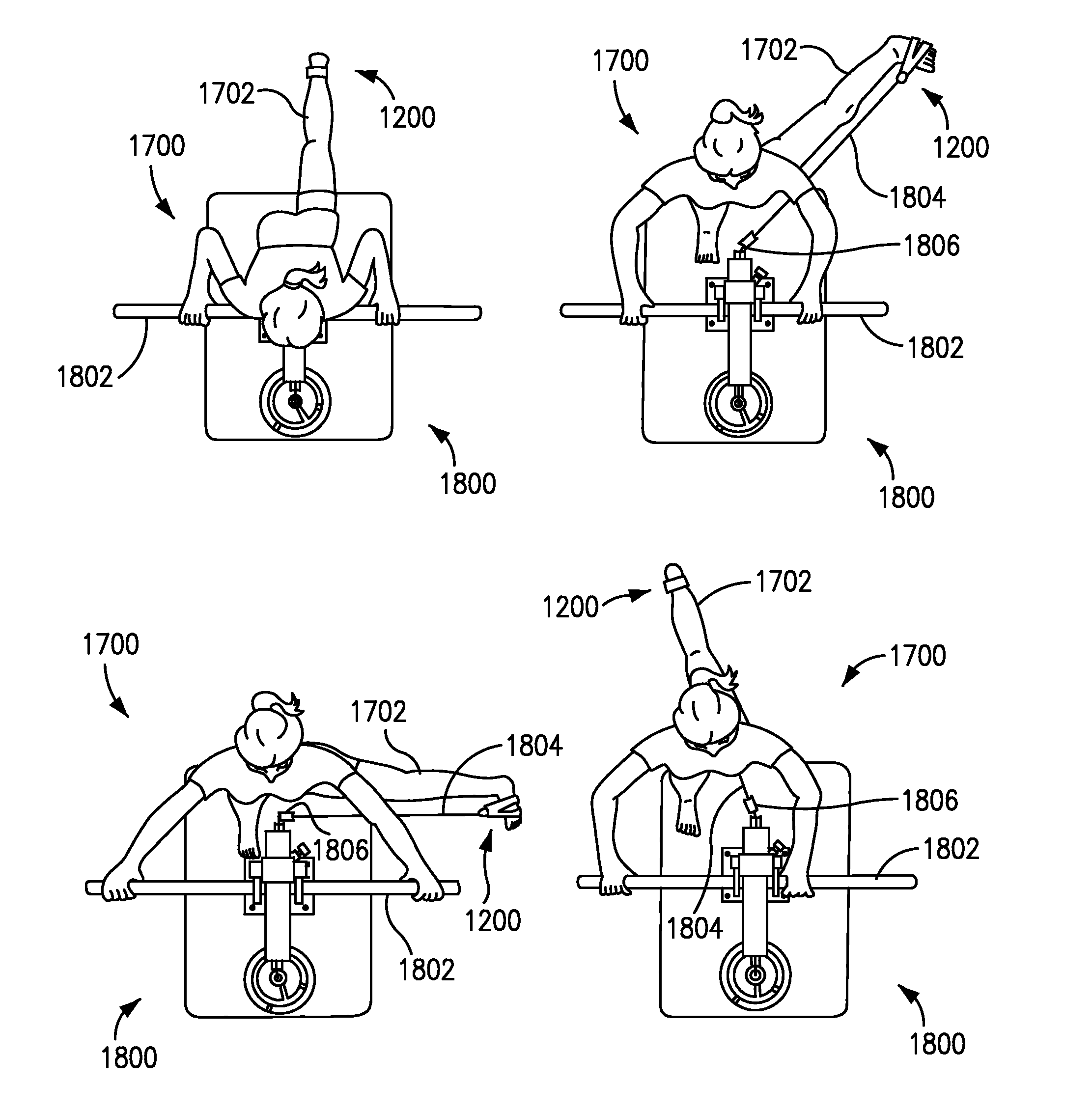
The present invention is an improved lower extremity receiving device that allows users to exercise their legs with maximum efficiency and convenience. The device can automatically securely wrap around a user's leg for hip extension and / or abduction exercise, and can be easily disengaged and engaged with the other leg without any manual effort. The device includes a self-standing sling that securely wraps around the user's foot and / or leg during exercise, and a resistance harness that delivers force of resistance during exercise. The device induces ideal exercise performance as the user naturally wraps the device around their leg and / or foot during exercise. Overall, this design allows users to switch between their legs during exercise, giving their opposite side gluteal muscles time to rest while maintaining the same overall exercise routine.

Problems solved by technology

However, several limitations prevent optimal gluteal exercise.
Furthermore, if the strap 100 succumbs to the force vector of the resistance-transmitting line, it can slip up the leg and disrupt exercise even further.
This is due to the fact that the ankle strap is more secure when the force vector is predominantly oriented radially outward, but less secure when the force vector is largely parallel to the leg.
Finally, the ankle strap requires that the force of resistance be applied at the position of the heel, thereby shortening the lever arm from the hip and rendering exercise less efficient.
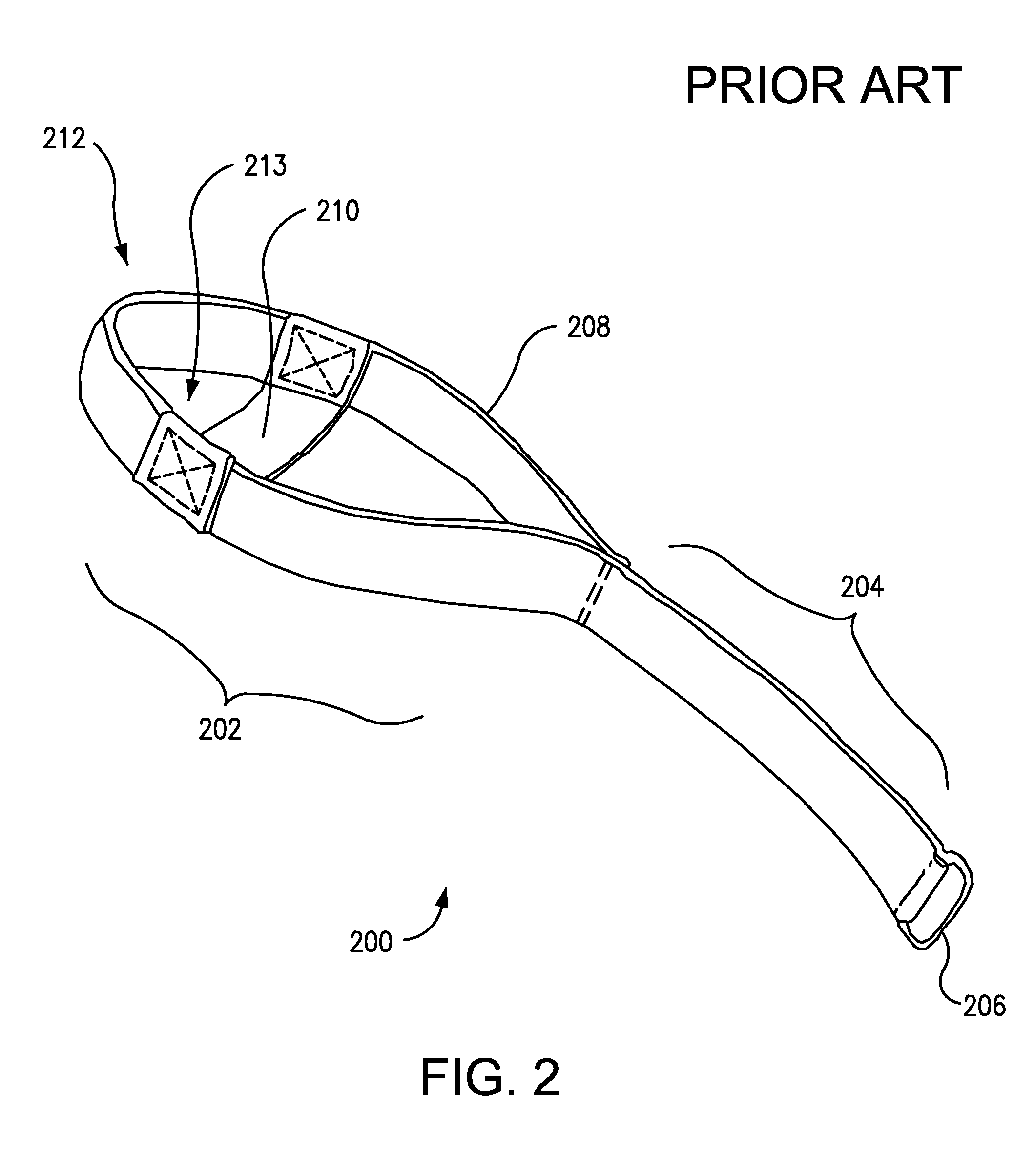
Nonetheless, a user of this set of straps 200 would still encounter considerable impediments to optimal gluteal exercise.
However, the greatest impediment to optimal gluteal exercise presented by this set of straps 200 is its inability to facilitate hip abduction exercise under resistance.
Simple adaptation of the straps of this device 200 would not solve the basic problem.
For example, if the cross band 210 were redesigned, repositioned or altogether removed, the device would no longer enable effective hip extension exercise.
The problem is the basic framework of the design itself.
This device 300 still requires considerable manual application for use with each exercising leg.
If such a design approach were followed in attempts to provide a hands-free pedal engagement experience, hip extension exercise would be severely compromised and full range of leg motion prevented.
Such an arrangement enables both parallel force and tripod posture for all exercises when performed from a single standing position, but this arrangement is not possible when the swivel 1602 is attached to the wall 1600.
These motions do not enhance gluteal development, but do enhance hip and core strength.

Method used


Image

  • Lower extremity receiving device for providing enhanced leg mobility during lower body exercise
  • Lower extremity receiving device for providing enhanced leg mobility during lower body exercise
  • Lower extremity receiving device for providing enhanced leg mobility during lower body exercise

Examples


embodiment 100

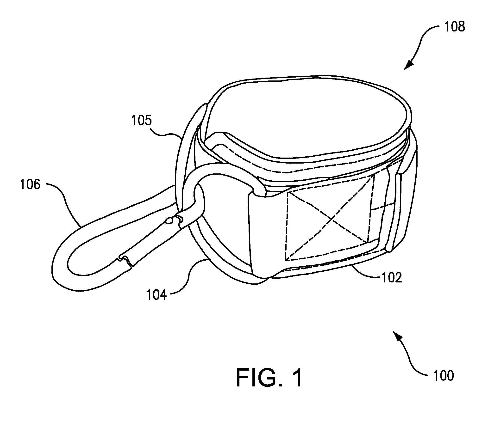
[0044]The ankle strap 100 is adjustable in the loop that it makes. The band 102 can be adjusted to fit snugly around a given user's posterior leg, at or adjacent to the ankle area. While the embodiment 100 shown makes use of a hook-and-loop system (e.g., Velcro), other adjustment means can be contemplated, such as a belt for example. The rings 104, 105 shown in FIG. 1 are D-rings. Their semicircular shape allows the locking loop 106 to slide up and down their extent, enabling a user to exercise their leg in a variety of ways, under resistance.

[0045]These functionalities make the ankle strap 100 considerably useful for hip extension and / or hip abduction exercises, which strengthen the gluteal muscles. However, several limitations prevent optimal gluteal exercise. Although it is advantageous to switch legs frequently during exercise, this strap 100 must be meticulously applied manually to each leg, either by using two straps, applying one to each legs and switching the line from one l...

embodiment 400

[0057]FIG. 4 is an unembellished illustrative embodiment 400 of the invention. The embodiment shown 400 comprises a self-standing sling configured to wrap securely around a portion of a user's lower extremity, and a resistance harness connected to the sling and capable of delivering resistance to the sling. The sling includes a supportive scaffold 402 to help the sling stand up and open. The resistance harness shown includes a band 404 connected to the sling, and a ring 406 for engaging a resistance-transmitting line 407 and thereby facilitating delivery of force of resistance from the line 407 to the sling.

[0058]The sling further includes a heel socket 408 for receiving a user's heel in the case of hip extension exercise. The heel socket 408 shown here is a circular hole, but it can take other structural forms and / or assume other shapes, as further shown and described below. In the case of substantial hip abduction exercise, the heel socket 408 is not used in its capacity to hold t...

embodiment 800

[0084]FIG. 8 is a rear oblique view of an embodiment 800 of the invention wrapped around a user's posterior leg and foot during hip extension exercise. A user pulls their exercising leg 802 back to extend their hip, while the device 800 absorbs resistance from a resistance-transmitting line 804 in communication with a pulley 806. The device 800 includes a supportive scaffold with two supportive walls 808, 809 and an upper band with two loops 810, 811 for housing a belt harness 812. A ring 814 connects the belt harness 812 to the resistance-transmitting line 804, enabling the belt harness 812 to deliver resistance to the device 800. The belt 812 is circumference-adjustable by a buckle 816.

[0085]The user is able to engage the device 800 with their foot without manual effort, and extend their hip through full range of motion. A heel strap 818 hooks under the heel 820 of the user's foot 822, and secures the device 800 to the user's foot throughout the entire duration of hip extension, a...


PUM


Abstract

A lower extremity receiving device is disclosed, which facilitates enhanced gluteal muscle engagement, body stability, and range of motion. The device includes a self-standing sling that can stand upright and ready to receive a user's lower extremity and enable them to commence any combination of hip extension or hip abduction with proper form upon inserting their foot, the sling including a heel socket that surrounds and facilitates rotational movement of the user's heel during the applicable hip extension exercise, and a resistance harness connected to the sling and capable of engaging a resistance-transmitting line for exercise, the harness having a clearance space for providing clearance for a user's foot as they alternately insert or remove their foot. This functional framework of elements enables a user to perform full range of combination of hip extension and hip abduction under resistance, via hands-free insertion of either foot into the sling.

Description

CROSS-REFERENCE TO RELATED APPLICATIONS[0001]This application claims the benefit of U.S. Provisional Application No. 62 / 060,556, filed Oct. 6, 2014. This application is also related to co-pending applications which also claim benefit of the above-named provisional application, the co-pending applications having the docket numbers KAMINS-002 and KAMINS-003, filed on behalf of the same inventor: Paul Kamins.FIELD[0002]The invention relates generally to fitness equipment, and more particularly to devices for lower body exercise.BACKGROUND[0003]In addition to being an integral part of an individual's overall physical fitness, toned and shapely buttocks and legs have also become desirable due to their perceived physical attractiveness. As a result, the market for lower body exercise machines and devices has grown in recent years, especially among women. Many such machines and devices are known in the art.[0004]One approach to exercising the lower body involves use of a resistance-transmi...

Claims


Application Information

Patent Timeline
Patent Type & Authority Applications(United States)
IPC IPC(8): A63B21/04A63B23/04
CPCA63B21/0442A63B23/0488A63B23/04A63B21/00069A63B21/0552A63B21/0557A63B21/154A63B23/03508A63B23/0482A63B2208/0204A63B2208/0209A63B2209/10A63B2210/50A63B21/0628A63B21/169A63B21/4013A63B21/4015A63B21/4039A63B21/4043
Inventor KAMINS, PAUL
Owner KAMINS PAUL
Learn More