Display device and television receiver

Inactive Publication Date: 2016-06-09
SHARP KK
View PDF1 Cites 5 Cited by
  • Summary
  • Abstract
  • Description
  • Claims
  • Application Information

AI Technical Summary

Benefits of technology

The invention is a display device with a divided frame and connectors that can be easily assembled and disassembled. The use of extruded materials like aluminum reduces mold costs, and the female screws in the connectors prevent screw damage and reduce replacement costs. The screws are arranged close to the frame, and the connector is designed to prevent chips from entering the display panel. These features improve productivity, workability, and appearance quality while reducing overall costs.

Problems solved by technology

The cost of the mold is in direct proportion to the size of the front cabinet, and in large models, the cost of the mold becomes higher.
Further, in a case of expanding the large models in a plurality of variations, the mold costs are increased by the number of models.
However, since the frame members are made of a soft metal material such as aluminum, or the like which is likely to cause screw damage, defective products often occur due to fastening failure or the like.
When defective products occur, a new frame member is required for replacing the same, and it has been a factor to which F cost (cost for the occurrence of the defective products) is significantly increased.
As a measure for this, when a torque of the screw is set to be weak, since the torque of the screw is different from the other parts, it is necessary to manage the torque of the connecting portions and the torque of the other parts separately, and thereby there are problems in which productivity and workability may be deteriorated.
In addition, when making the screw damage less likely to occur by increasing the length of the screw, there is a problem that a set thickness of the TV receiver may be increased.
Further, in the conventional connecting structure, since the thick projection 65c, or the like is required for fixing the screw to the frame member made of aluminum, the cross-section of the frame member may become non-uniform so as to cause deterioration in appearance of product and an increase in unit costs.
That is, in the conventional connecting structure, the root of the projection 65c becomes thick, and flow of the material is not uniform during forming of the frame member, thereby there is a problem that warping and sink (thick part is recessed) may easily occur in the frame member, and quality control may become difficult so as to cause a decrease in productivity.

Method used


Image

  • Display device and television receiver
  • Display device and television receiver
  • Display device and television receiver

Examples


embodiment 1

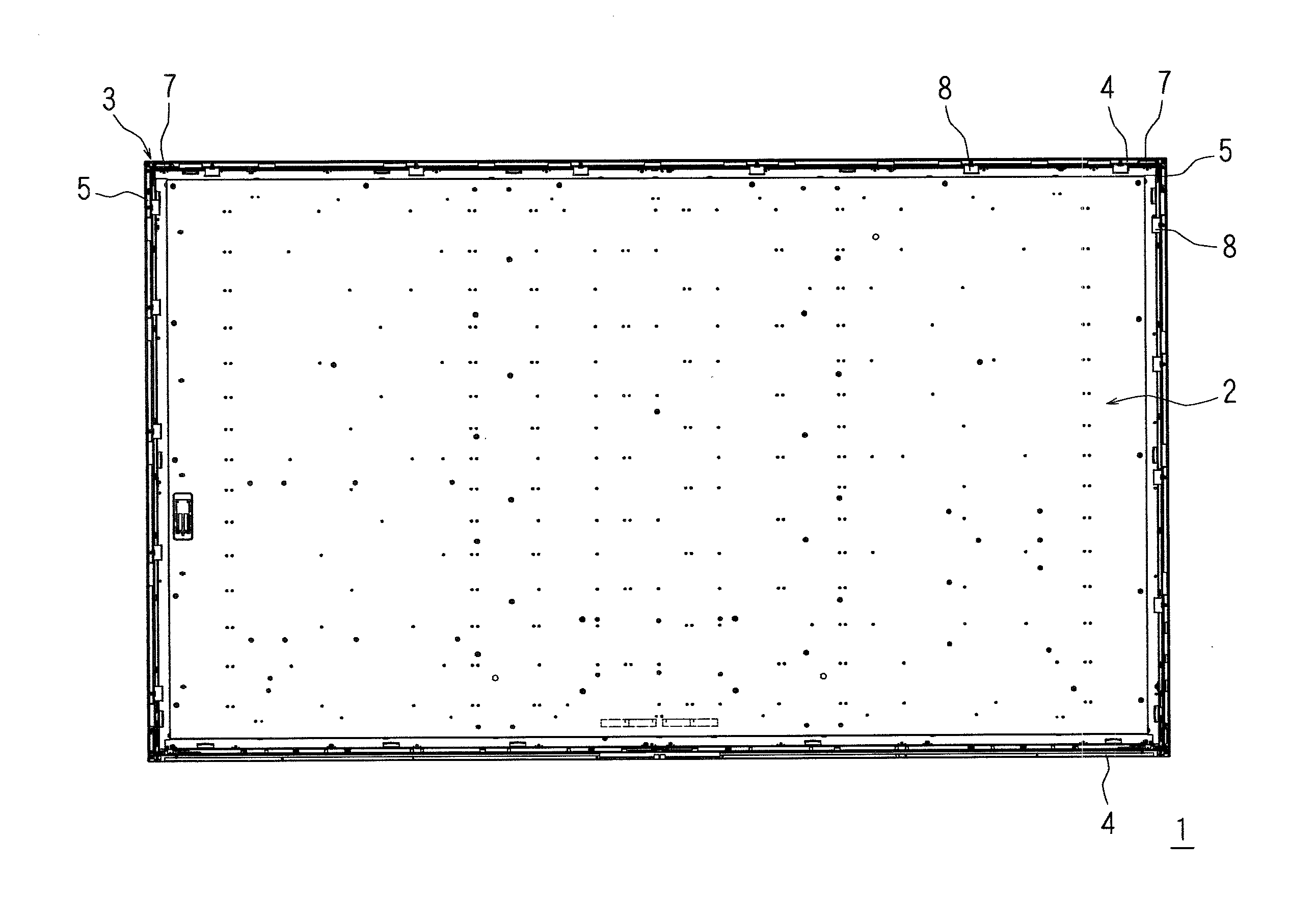
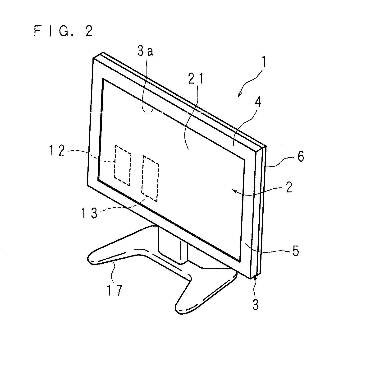
[0058]FIG. 2 is a perspective view illustrating a front appearance of a television receiver 1 (hereinafter, referred to as a TV receiver) according to Embodiment 1 of the present invention, FIG. 3 is a rear view illustrating a state in which a rear cabinet of the TV receiver 1 according to Embodiment 1 of the present invention is removed, FIG. 4 is a partially enlarged view of FIG. 3, FIG. 5 is a partial longitudinal sectional view illustrating a state in which the rear cabinet is removed, FIG. 6 is a rear view illustrating a front cabinet, FIG. 7 is a partially enlarged view of FIG. 6, and FIG. 8 is a perspective view of a portion of FIG. 7.

[0059]The TV receiver 1 includes a laterally long display module 2 for displaying an image thereon, a tuner 12 which is disposed in the display module 2 to receive a broadcast wave from an antenna (not illustrated), and a decoder 13 which is disposed in the display module 2 to decode the encoded broadcast wave. In the TV receiver 1, the decoder ...

embodiment 2

[0097]A TV receiver 60 according to Embodiment 2 of the present invention has the same configuration as the TV receiver 1 according to Embodiment 1, except that the structure of a horizontal frame 64 and a vertical frame is different therefrom.

[0098]FIG. 16 is a partial longitudinal sectional view illustrating the TV receiver 60 according to Embodiment 2 of the present invention. In the drawings, the same parts as FIG. 5 will be denoted by the same reference numerals, and will not be described.

[0099]The horizontal frame 64 of the TV receiver 60 includes an end edge covering part 64a which extends in a plate shape so as to be along a long side of the display module 2, a side covering part 64b which is continuously arranged so as to be orthogonal to the end edge covering part 64a, and extends in the plate shape so as to be along the side part of the display module 2. Unlike the horizontal frame 4 according to Embodiment 1, the side covering part 64b is not provided with the protruding...

embodiment 3

[0104]A TV receiver according to Embodiment 3 of the present invention has the same configuration as the TV receiver 1 according to Embodiment 1, except that the structure of a connector 80 is different therefrom.

[0105]FIG. 17 is a perspective view illustrating a state in which a second plate part 82 of the connector 80 according to Embodiment 3 of the present invention is inserted between the protruding part 53 and the end edge covering part 51 of the vertical frame 5, FIG. 18 is a partial cross-sectional view of the second plate part 82, and FIG. 19 is a perspective view illustrating a state in which the protruding part 53 is screwed to the second plate part 72. In the drawings, the same parts as FIGS. 12 and 13 will be denoted by the same reference numerals, and will not be described.

[0106]The connector 80 according to Embodiment 3 is made of stainless steel, and formed in an L shape. A first plate part 81 and the second plate part 82 forming each side of the L shape are differen...


PUM


Abstract

Provided are a display device capable of suppressing occurrence of defective products due to fastening defect of screws, having excellent productivity and workability, achieving narrowing of frame and thinning of set thickness with excellent appearance quality, and manufacturing at a low cost, as well as a television receiver including the display device. A TV receiver includes a display module, and horizontal frames which cover long side peripheral end part of a front surface of the display module. A first plate part and a second plate part forming each side of L-shaped connectors are provided with a plurality of female screws. The horizontal frame includes an end edge covering part which covers long side end edge part of the display module, and a side covering part which covers a side part thereof, and a protruding part which protrudes inwardly of the side covering part. The protruding part is provided with a plurality of screw insertion holes. With the connector aligned to end portions of the horizontal frame and the vertical frame, screws are inserted into the screw insertion holes, and screwed to the female screws of the first plate part, and thereby the horizontal frame and the vertical frame are connected to each other.

Description

CROSS-REFERENCE TO RELATED APPLICATIONS[0001]This application is the national phase under 35 U.S.C. §371 of PCT International Application No. PCT / JP2013 / 66673 which has an International filing date of Jun. 18, 2013 and designated the United States of America.BACKGROUND[0002]1. Technical Field[0003]The present invention relates to a display device, in which a rectangular frame covering the peripheral edge part of a display unit is divided into four frame members such that end portions of the adjacent frame members are connected to each other by connectors, and a television receiver including the display device.[0004]2. Description of Related Art[0005]Recently, the size of a thin type television receiver (hereinafter, referred to as a TV receiver) including a liquid crystal display, or the like is becoming larger, and the number of models thereof such as 52, 60 and 70 inch display sizes is increasing as well. In this case, as the display size is becoming larger, and a cabinet (frame b...

Claims


Application Information

Patent Timeline
IPC IPC(8): H05K7/18H04N5/44H04N5/64
CPCH05K7/186H04N5/44H04N5/64G02F1/133308G02F1/13332G02F1/133328
Inventor IWATA, HIROKIYAMAMICHI, TOSHIHIRO
Owner SHARP KK
Why Eureka
Try Eureka