
Multi-stroke delivery pumping mechanism for a drug delivery device for high pressure injections

a pumping mechanism and drug technology, applied in the direction of suction devices, automatic syringes, intravenous devices, etc., can solve the problems of complex technique, difficult administration, and user's inability to easily deliver the drug to the intradermal region of the skin, etc., to facilitate the injection of insulin or other medicaments and achieve high pressure

Active Publication Date: 2016-06-09
BECTON DICKINSON & CO
View PDF7 Cites 2 Cited by
  • Summary
  • Abstract
  • Description
  • Claims
  • Application Information

AI Technical Summary

Benefits of technology

The device enables intradermal medication injections with lower input forces, reducing tissue damage and pain, and enhancing dose accuracy by decoupling the primary chamber from the injection mechanics, preventing leakage and inaccuracy issues.

Problems solved by technology

Such a technique is complicated, difficult to administer, and often may only be administered by an experienced health care professional.
However, a user would not be able to easily deliver the drug to the intradermal region of the skin, as discussed above.
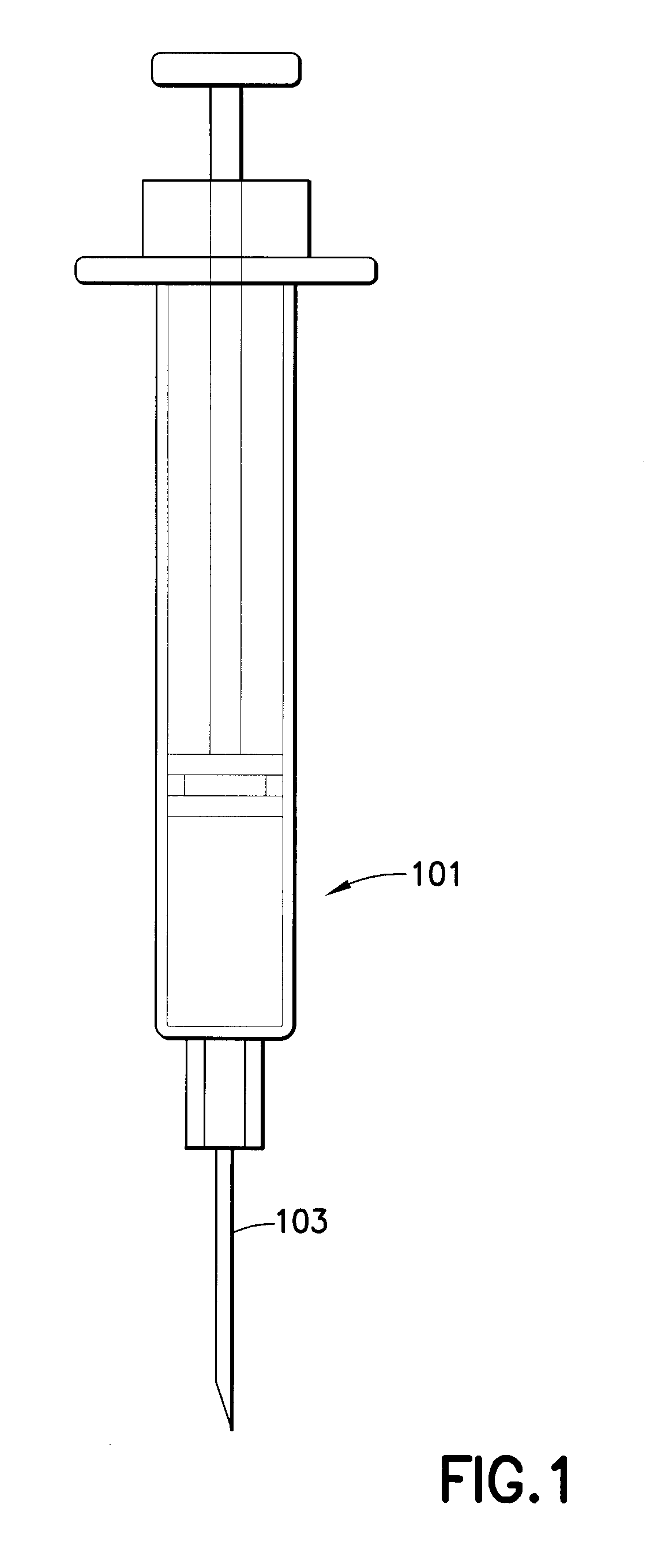
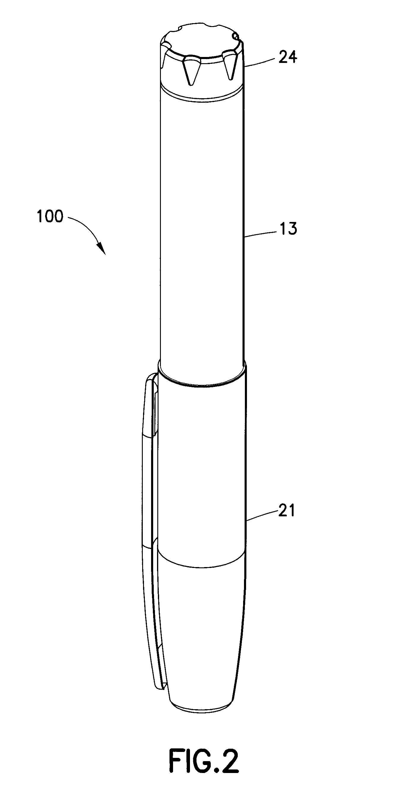
Existing drug delivery pens have several limitations regarding intradermal drug delivery.
First, the mechanical advantage provided by the pen is minimal and requires the user to supply upwards of 20 lbs of force to generate sufficient pressure.
Second, the pen components can be damaged by this high force, resulting in leaking and inaccuracy at the high pressures.
Existing drug delivery pens require a large force to inject medication into the intradermal layer, thereby making the intradermal medication injection difficult.
Furthermore, the drug delivery pen components can be damaged due to the high pressures associated with intradermal injections, thereby resulting in medication leakage and dose inaccuracy.

Method used


Image

  • Multi-stroke delivery pumping mechanism for a drug delivery device for high pressure injections
  • Multi-stroke delivery pumping mechanism for a drug delivery device for high pressure injections
  • Multi-stroke delivery pumping mechanism for a drug delivery device for high pressure injections

Examples


Embodiment Construction

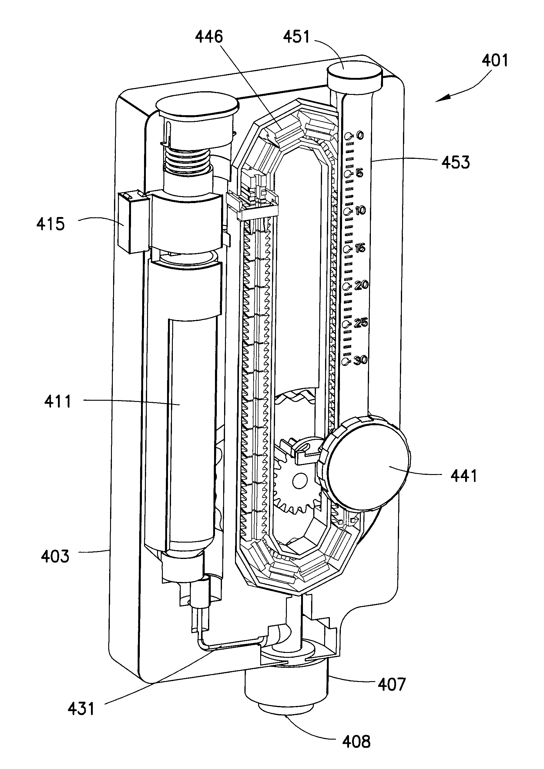
[0035]The drug delivery device according to exemplary embodiments of the present invention allows the user to inject a medicament dose at high pressures with lower input forces by decoupling the first chamber of a primary (original) medicament container and its cross sectional area from the injection mechanics.

[0036]Injecting a medicament dose in small packets or pulses, such as 10 μL, in succession, instead of at higher volumes can reduce the amount of pressure required for an intradermal injection. Reducing the pressure can result in less tissue damage and pain to the patient. Less pressure can also result in a lower required user force to intradermally inject the medication. Additionally, injecting a medicament dose in small doses or packets can provide improved dose accuracy over existing drug delivery pens, particularly at low dose ranges.

[0037]The presently disclosed drug delivery device has advantages in dose accuracy and medication leakage over existing drug delivery pens by...


PUM


Abstract

A dual-chambered drug delivery device, comprising a cartridge having a first chamber for storing a medicament, a second chamber in fluid communication with said first chamber, a dose setting member for setting a medicament dose to be injected at an injection site, a piston disposed in said second chamber, an upward stroke of said piston drawing a portion of the medicament dose into said second chamber and a downward stroke of said piston expelling the portion of the medicament dose, a needle communicating with said second chamber for sequentially injecting portions of the medicament dose into the injection site, a drive screw movably connected to said dose setting member such that rotation of said dose setting member moves said drive screw upwardly, and a rack movably connected to said drive screw such that downward movement of said drive screw during the medicament dose injection rotates said rack.

Description

CROSS REFERENCE TO RELATED APPLICATIONS[0001]This application is a division of U.S. Nonprovisional application Ser. No. 12 / 998,840, filed Sep. 20, 2011, which is a U.S. national stage application under 35 U.S.C. §371 of International Application No. PCT / US09 / 06421, filed Dec. 8, 2009, which claims the benefit under 35 U.S.C. §119(e) of U.S. Provisional Application Ser. No. 61 / 193,594, filed Dec. 9, 2008, the entire disclosures of all of said prior applications being hereby incorporated by reference.FIELD OF THE INVENTION[0002]The present invention relates generally to a drug delivery device that facilitates high pressure medication injections. More particularly, the present invention relates to a drug delivery device that diverts high pressures away from the original drug container to prevent medicament leakage and inaccurate doses. Still more particularly, the present invention relates to injecting medication in small packets or pulses in succession to lower the force required to i...

Claims


Application Information

Patent Timeline
Patent Type & Authority Applications(United States)
IPC IPC(8): A61M5/48A61M5/20A61M5/315A61M5/142
CPCA61M5/48A61M5/14216A61M2005/3152A61M5/31511A61M5/31553A61M5/204A61M5/286A61M5/3146A61M5/3158A61M2005/3128A61M2005/31518
Inventor SCHOONMAKER, RYANBRUEHWILER, MICHELSPOOL, IRAROSEN, MELISSA
Owner BECTON DICKINSON & CO
Learn More