Light-receiving device and method for producing the same
a light-receiving device and light-receiving technology, which is applied in the direction of semiconductor devices, photovoltaic energy generation, electrical apparatus, etc., can solve the problems of difficult to separate pixels, difficult to uniformly perform selective diffusion over large-diameter wafers, and difficult to planar-type photodiodes formed by selective diffusion, etc., to achieve satisfactory crystallinity, easy decomposition, and satisfactory crystallinity
- Summary
- Abstract
- Description
- Claims
- Application Information
AI Technical Summary
Benefits of technology
Problems solved by technology
Method used
Image
Examples
first embodiment
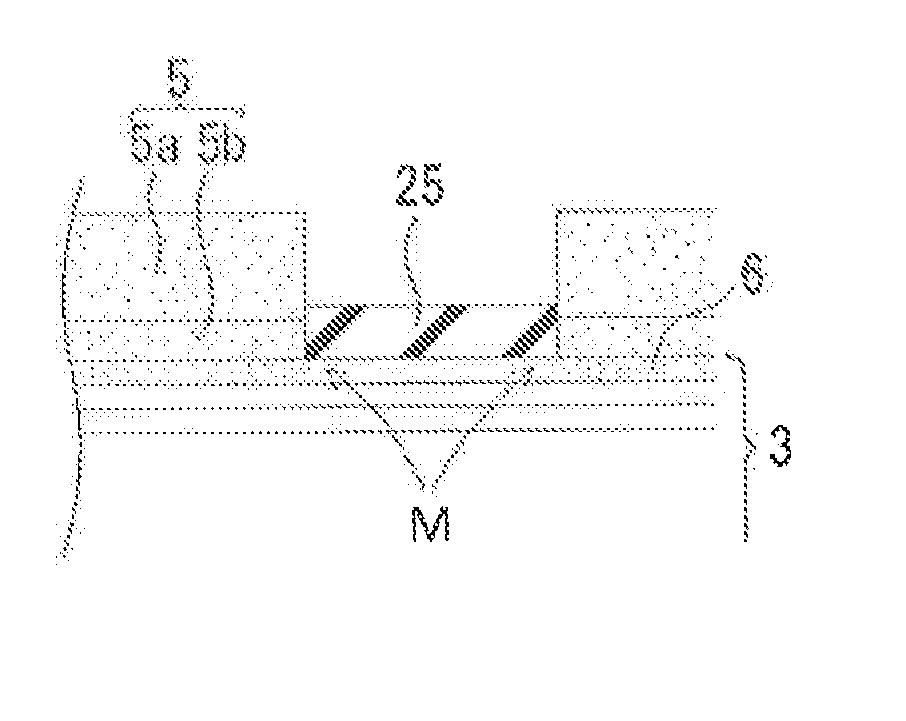
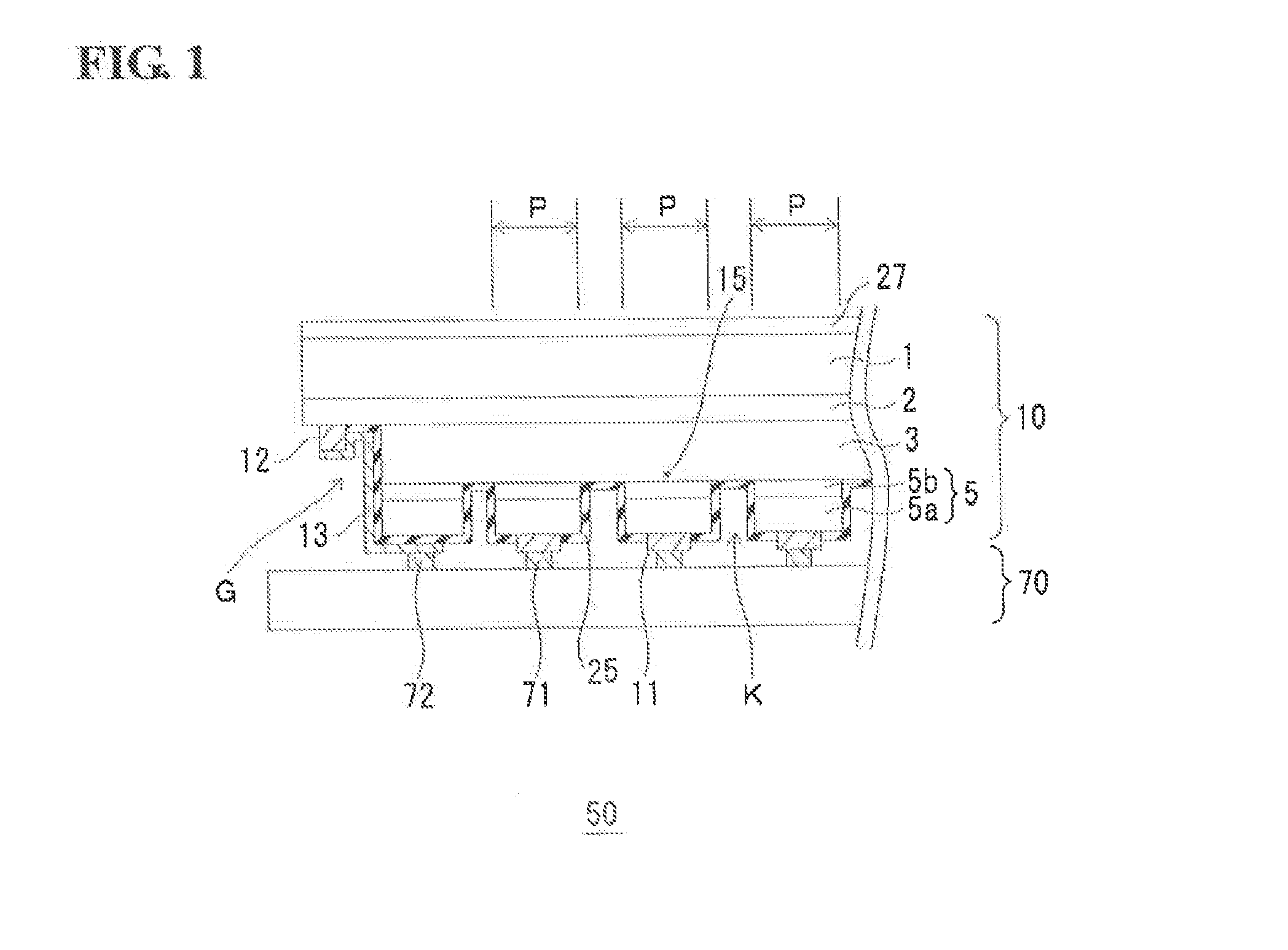
[0043]FIG. 1 illustrates a sensing apparatus 50 including a light-receiving device 10 and a read-out integrated circuit (ROIC) 70 connected to the light-receiving device 10. The light-receiving device 10 has a stacked semiconductor layer described below, (InP substrate 1 / n-type InP buffer layer 2 / light-receiving layer 3 / cap layer 5). The light-receiving layer 3 includes an undoped multi-quantum well (MQW) structure in which well layers and barrier layers are alternately stacked. Especially, the light-receiving layer 3 includes an undoped type-II multi-quantum well (MQW) structure. The light-receiving layer 3 including the type-II multi-quantum well (MQW) structure is explained hereinafter.
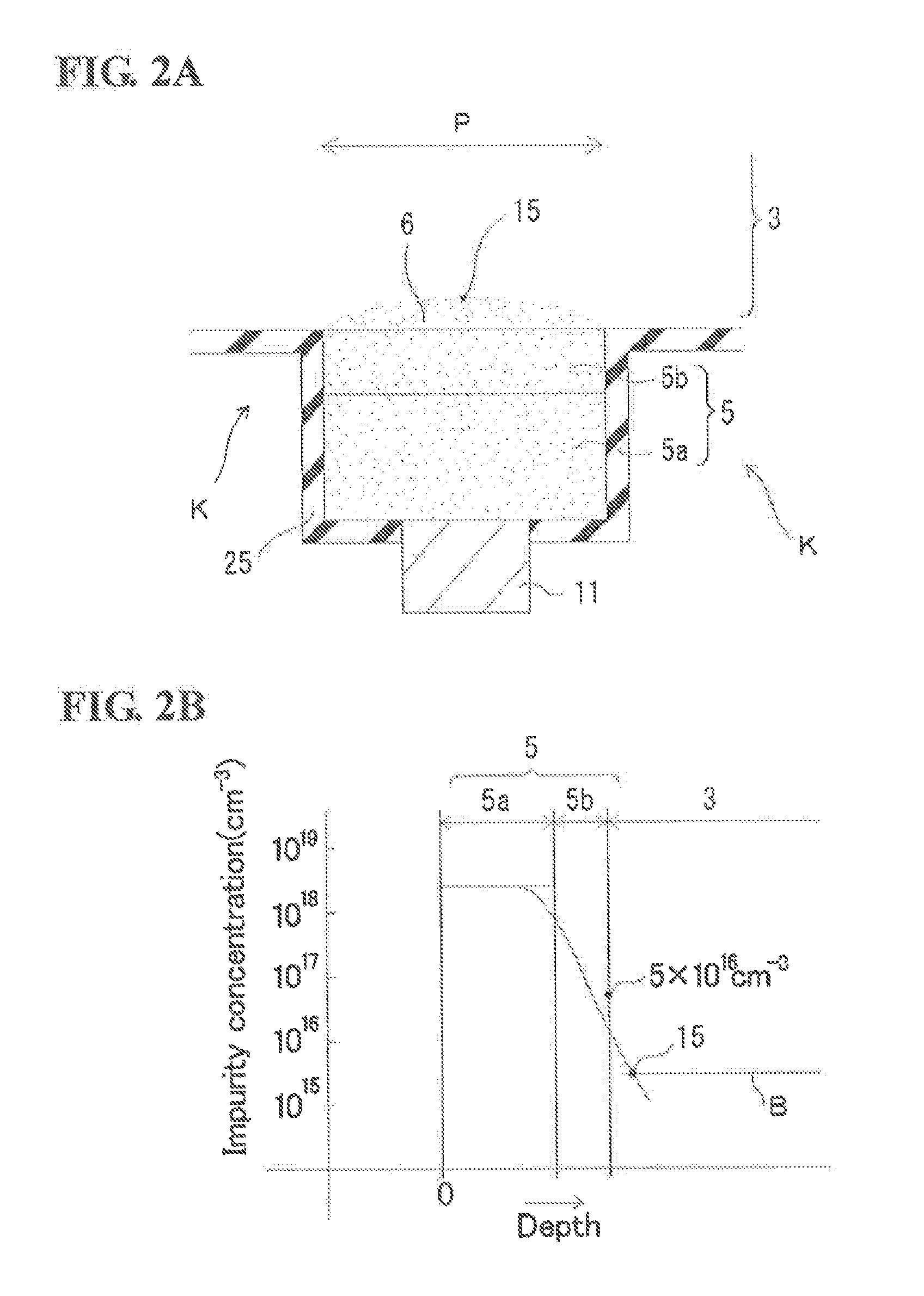
[0044]The cap layer 5 includes a p-type InGaAs contact layer 5a and an InGaAs concentration adjusting layer 5b adjacent to the p-type InGaAs contact layer 5a. A pixel electrode 11 is formed on the p-type InGaAs contact layer 5a and is in ohmic contact with the p-type InGaAs contact layer 5a. Zinc (...
modified embodiment
[0055]FIGS. 3A and 3B illustrate a modified embodiment of the light-receiving device 10 illustrated in FIG. 1. FIG. 3A is a partially enlarged cross-sectional view of the pixel P. FIG. 3B illustrates the in-depth distribution of the concentration of Zn serving as a p-type impurity. The difference between the modified embodiment and the light-receiving device 10 illustrated in FIGS. 1 and 2 is that a trench K is deepened in such a manner that the bottom of the trench K is located at a position 3b in the light-receiving layer 3. When the trench K is deepened to the light-receiving layer 3, the position of the bottom is located at a position in the light-receiving layer 3 away from the boundary between the concentration adjusting layer 5b and the light-receiving layer 3 by 2 / 10 or less of the thickness of the light-receiving layer. As illustrated in FIG. 3A, the deep mesa trench K increases a region where the depth position of the p-n junction 15 lies at a shallower depth than the dept...
second embodiment
[0065]FIG. 6 illustrates the sensing apparatus 50 in which the light-receiving device 10 according to a second embodiment is connected to the read-out integrated circuit (ROIC) 70. The difference from the light-receiving device 10 according to the first embodiment is that the cap layer 5 is formed of the p-type contact layer 5a alone without the concentration adjusting layer in this embodiment. The bottom of the trench K of the mesa structure is located at a position away from the upper surface of the light-receiving layer 3 by 20% or less of the thickness of the light-receiving layer 3.
[0066]FIG. 7A is a partially enlarged view of a pixel P illustrated in FIG. 6. FIG. 7A also illustrates a cross-sectional view of the distribution of Zn serving as a p-type impurity in the pixel P. In the embodiment, the pixels P are mechanically and structurally separated from each other by the trench K of the mesa structure. FIG. 7B illustrates the in-depth distribution of Zn concentration. In the ...
PUM
 Abstract
Description
Claims
Application Information
 - R&D
- Intellectual Property
- Life Sciences
- Materials
- Tech Scout
- Unparalleled Data Quality
- Higher Quality Content
- 60% Fewer Hallucinations
Browse by: Latest US Patents, China's latest patents, Technical Efficacy Thesaurus, Application Domain, Technology Topic, Popular Technical Reports.
© 2025 PatSnap. All rights reserved.Legal|Privacy policy|Modern Slavery Act Transparency Statement|Sitemap|About US| Contact US: help@patsnap.com


