Image encoding apparatus, image encoding method, recording medium and program, image decoding apparatus, image decoding method, and recording medium and program
a technology of image encoding and decoding, which is applied in the direction of signal generator with optical-mechanical scanning, color television with bandwidth reduction, etc., can solve the problem of not being able to independently encode and decode only the tiles corresponding to the position of the mcts
- Summary
- Abstract
- Description
- Claims
- Application Information
AI Technical Summary
Benefits of technology
Problems solved by technology
Method used
Image


Examples
first embodiment
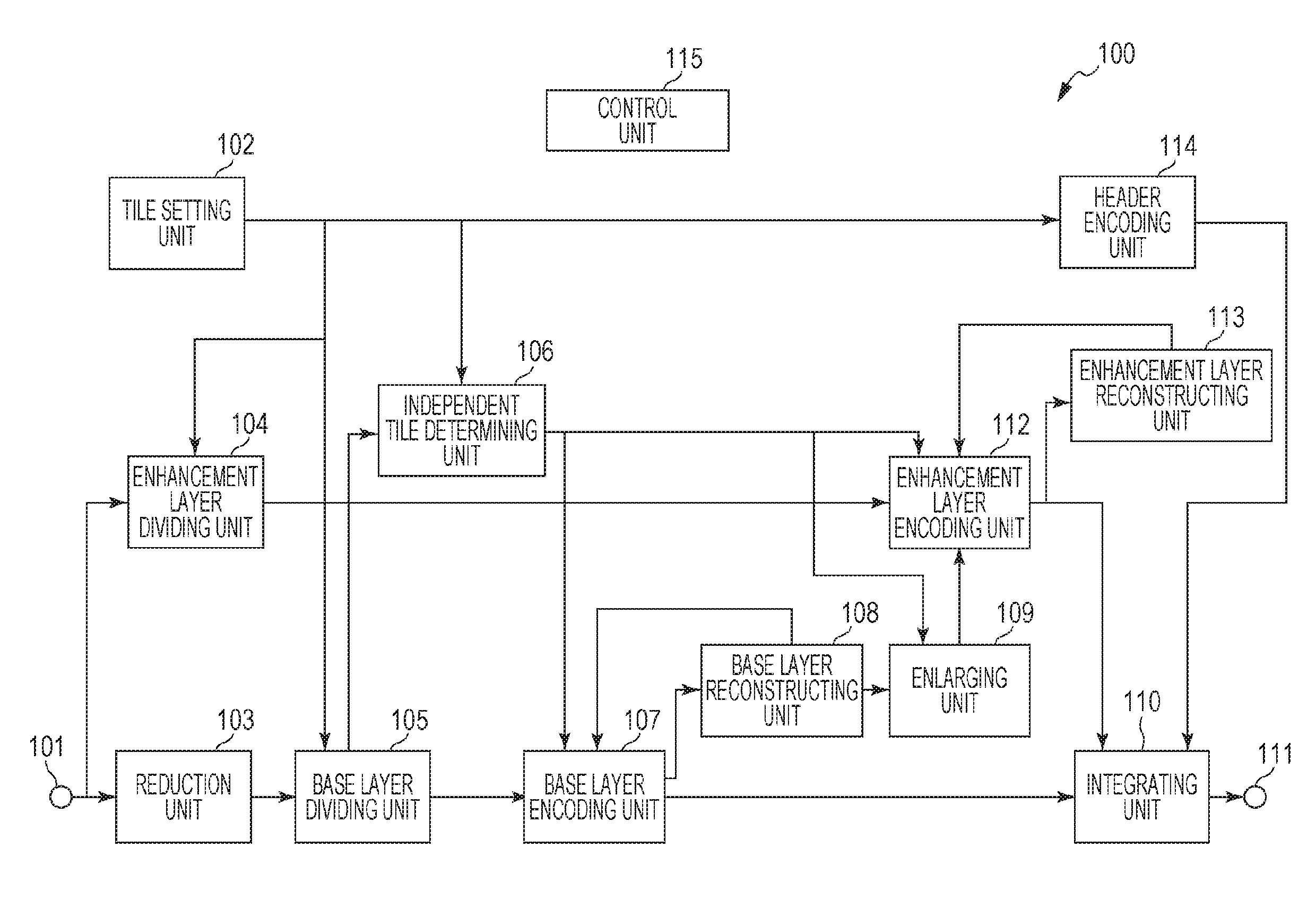
[0038]An outline of each processing unit composing an image encoding apparatus according to a first embodiment will now be described with reference to FIG. 1. FIG. 1 is a block diagram illustrating an example of the configuration of an image encoding apparatus 100 of the first embodiment.
[0039]Referring to FIG. 1, an image (an input image) is input into the image encoding apparatus 100 through a terminal 101 (an input unit). The input image is input for each frame. A tile setting unit 102 determines the number of tiles horizontally divided in one frame, the number of tiles vertically divided in one frame, and the position of each tile. In addition, the tile setting unit 102 determines which tile, among the tiles resulting from the division, is encoded as the independent tile. Information indicating the number of tiles horizontally divided, the number of tiles vertically divided, and the position of each tile, which are set by the tile setting unit 102, is hereinafter referred to as ...
second embodiment
[0110]An outline of each processing unit composing an image decoding apparatus according to a second embodiment will now be described with reference to FIG. 6. FIG. 6 is a block diagram illustrating an example of the configuration of an image decoding apparatus 600 including an image decoding unit 605 of the second embodiment. A case in which the bit stream generated in the first embodiment is decoded is exemplified in the second embodiment.
[0111]Referring to FIG. 6, the bit stream is input into the image decoding apparatus 600 by communication, etc. through an interface 601. A storage unit 602 stores the bit stream supplied from the interface 601 and bit streams that are recorded in advance. A display control unit 603 specifies a method of displaying the bit stream instructed by the user. The display control unit 603 supplies a layer (hierarchy) to be decoded and an area (display area) to be decoded to the image decoding unit 605 as a display control signal. Although the layers to ...
third embodiment
[0212]The processing units illustrated in FIG. 1, FIG. 4, FIG. 6, FIG. 7, and FIG. 9 are configured as hardware in the first embodiment and the second embodiment. However, the processes performed in the processing units may be executed by computer programs.
[0213]FIG. 11 is a block diagram illustrating an exemplary hardware configuration of a computer that executes the processing in each processing unit in the image encoding apparatus according to the first embodiment and the image decoding apparatus according to the second embodiment.
[0214]Referring to FIG. 11, a central processing unit (CPU) 1101 controls the entire computer using computer programs and data stored in a random access memory (RAM) 1102 and a read only memory (ROM) 1103 and executes the processes described above performed by the image encoding apparatus according to the first embodiment and the image decoding apparatus according to the second embodiment. In other words, the CPU 1101 functions as each processing unit i...
PUM
 Abstract
Description
Claims
Application Information
 - R&D
- Intellectual Property
- Life Sciences
- Materials
- Tech Scout
- Unparalleled Data Quality
- Higher Quality Content
- 60% Fewer Hallucinations
Browse by: Latest US Patents, China's latest patents, Technical Efficacy Thesaurus, Application Domain, Technology Topic, Popular Technical Reports.
© 2025 PatSnap. All rights reserved.Legal|Privacy policy|Modern Slavery Act Transparency Statement|Sitemap|About US| Contact US: help@patsnap.com