Position detection device, position detection system, and position detection method
a technology of position detection and current position, applied in the direction of measurement devices, instruments, satellite radio beaconing, etc., can solve the problem that the position detection device cannot precisely output any current position, and achieve the effect of stably determining and outputting current positions, low cost, and short tim
- Summary
- Abstract
- Description
- Claims
- Application Information
AI Technical Summary
Benefits of technology
Problems solved by technology
Method used
Image
Examples
first embodiment
[0095]FIG. 5 is a view showing a locus of current positions detected by the first method in the present invention.
[0096]Raw data of the pseudo range is simply derived by multiplying the signal propagation time and the light velocity. Though, the pseudo range has to be corrected, since the signal propagation time includes various errors. The pseudo range Rn calculated regarding a nth positioning satellite 41 is expressed as the following Equation (2).
Rn=ρn+c(δtr−δTn)+In+Tn+εn Equation (2)
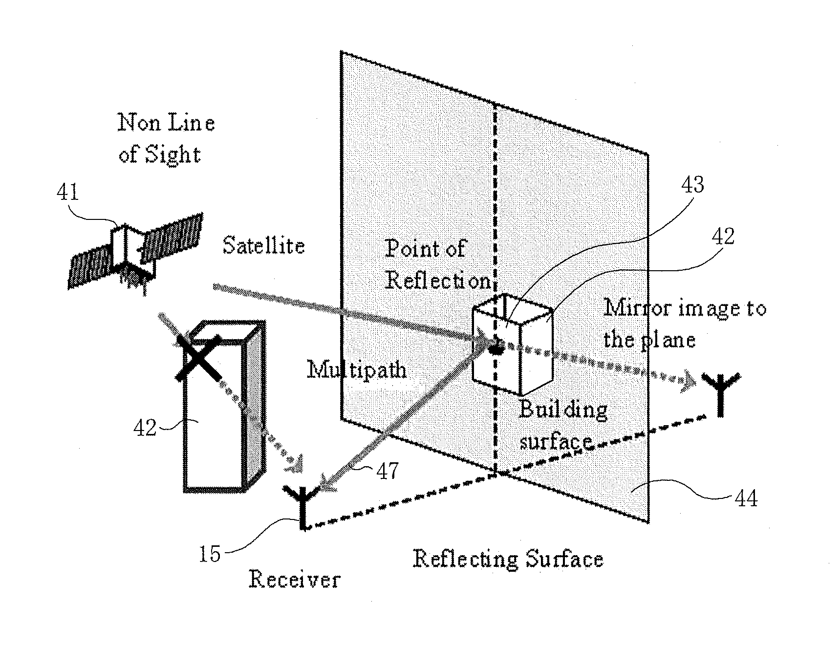
[0097]In Equation (2), ρn denotes a geometric distance to the nth positioning satellite 41, δTn denotes a time delay of a satellite clock from GPS time scale, I denotes a delay distance due to ionosphere, T denotes a delay distance due to troposphere, and ε denotes errors due to multipath, a noise of the receiving unit 12 and a delay of the antenna 15.
[0098]The time delay of the satellite clock from GPS time scale is corrected using values calculated based on the broadcast ephemeris. The delay dist...
third embodiment
[0157]FIG. 11 is a set of views illustrating a relation between a NLOS path and a LOS path and edges of a structure in the present invention. In FIG. 11, (a) shows a case where the path goes outside the structure, and (b) shows a case where the path is interrupted by the structure.
[0158]In this embodiment, position presumption is performed in consideration of an error model of structure. Therefore, regarding a structure, in case that a ray or a path goes through a fixed range from edges of the structure illustrated by a digital surface model or something, which is a database of measured shape or something of the structure, both LOS and NLOS are presumed and calculated, then likelier one is distinguished.
[0159]Specifically, the NLOS reflected path estimating part 24 performs a judgment whether the positioning satellite 41 within vision from the current position of the position detection device 11 is LOS or NLOS, before estimating the error of the multipath based on the ray-tracing me...
fourth embodiment
[0167]FIG. 12 is a view showing an example of probability of NLOS in the present invention.
[0168]In this embodiment, similarly to the third embodiment, position presumption is performed in consideration of an error model of structure. Though, according to this embodiment, the error model is posited on positions of edges of the structure, and, in a case that the ray goes near the edges of the structure, the probability of NLOS and LOS is defined by the error model, instead of setting the threshold dthreshold about the minimum distance dmin between the edges of the structure and the ray as in the third embodiment. That is, the probability of NLOS and LOS corresponding to the minimum distance dmin is defined. Then, the probability is inserted in a position presumption model like the particle filter explained in the second embodiment.
[0169]Specifically, assuming that the direction from the edge of the structure to outside denotes positive and that the minimum distance between the edges ...
PUM
 Abstract
Description
Claims
Application Information
 - R&D
- Intellectual Property
- Life Sciences
- Materials
- Tech Scout
- Unparalleled Data Quality
- Higher Quality Content
- 60% Fewer Hallucinations
Browse by: Latest US Patents, China's latest patents, Technical Efficacy Thesaurus, Application Domain, Technology Topic, Popular Technical Reports.
© 2025 PatSnap. All rights reserved.Legal|Privacy policy|Modern Slavery Act Transparency Statement|Sitemap|About US| Contact US: help@patsnap.com


