Method for operating a combined cycle power plant

a combined cycle and power plant technology, applied in the direction of machines/engines, mechanical equipment, light and heating equipment, etc., can solve the problems of increasing the pressure on the conventional power plant, so as to reduce the pressure, reduce the service life, and reduce the pressur

Inactive Publication Date: 2016-05-26
SIEMENS AG
View PDF3 Cites 5 Cited by
  • Summary
  • Abstract
  • Description
  • Claims
  • Application Information

AI Technical Summary

Benefits of technology

[0010]The invention thus proposes indicating an operating method wherein the steam turbine is involved in the parked load. Thus, for the purposes of grid stability, the steam turbine rotor keeps as much rotating mass as possible on the grid.
[0011]The ST power of the steam turbine is reduced to a very low power shortly before the planned commencement of the parked load. The gas turbine is then operated in parked load. On account of the markedly lower heat transfers between steam and steam turbine components in part load, service life consumption is significantly lower as a consequence of lowering the steam temperature. In that context, the steam turbine cools down slowly.
[0018]Thus, ideally, one pressure stage is completely closed. In the switched-off turbine section, the service life consumption is even lower since here the components cool down naturally. Advantageously, the pressure in the steam turbine or in the remaining operational turbine sections is reduced as much as possible, which is made possible by drains, evacuation lines, start-up lines or also process steam lines.
[0019]Thus, the significant reduction in the pressure in the steam turbine reduces the heat transfer and significantly reduces the service life consumption during part load.

Problems solved by technology

Feeding-in of the renewable energies is subject to fluctuations, which leads to increasing demands on the conventional power plants.
However, this means that the hot components of the steam turbine are exposed to cold steam, which leads to thermal stresses.
If the parked load is then abandoned again, the steam temperatures rise again, which once again leads to thermal stresses.
This would lead to very low service life consumption.

Method used


Image

  • Method for operating a combined cycle power plant
  • Method for operating a combined cycle power plant

Examples


Embodiment Construction

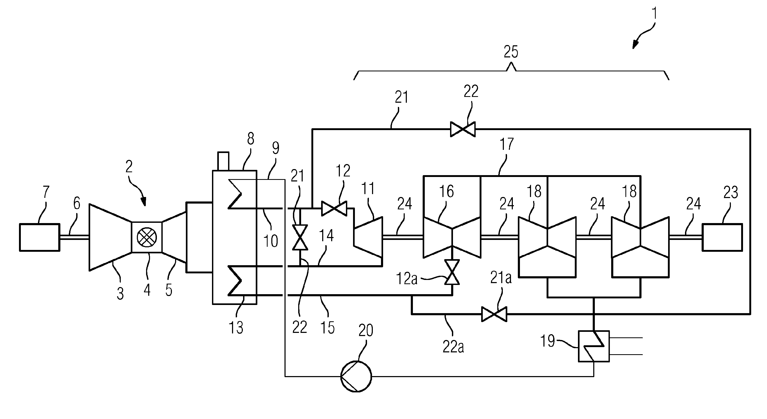
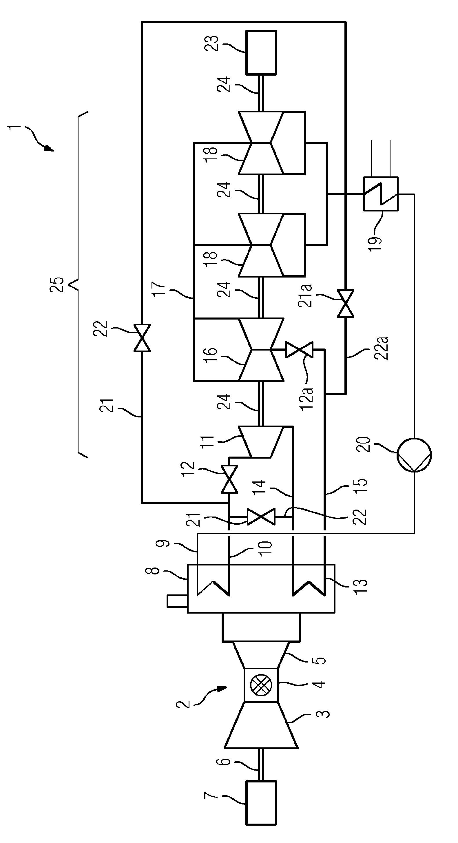
[0022]FIG. 1 shows a schematic representation of a combined cycle power plant. In essence, a combined cycle power plant 1 comprises a gas turbine 2 that can be operated with fossil fuels. This gas turbine 2 comprises a compressor part 3 in which air is heated and compressed, a combustion chamber 4 in which the air from the compressor part 3 is mixed with fuel and ignited, and a turbine part 5 in which—in various stages consisting of guide vanes and rotor blades that are not shown—the hot exhaust gases turn a rotor. A shaft 6 transfers this rotation to a generator 7. The generator 7 then supplies a supply grid with electrical energy (not shown).

[0023]The hot exhaust gases from the gas turbine 2 are fed into a steam generator 8. In this steam generator 8, fresh steam is generated by means of a line 9 and is then fed via a steam turbine fresh steam line 10 into a high-pressure turbine section 11. An HP valve 12 is arranged in the steam turbine fresh steam line 10. The steam leaving the...


PUM


Abstract

A method for operating a combined cycle power plant, according to which shortly before the planned start-up of a parked load, the steam turbine is lowered to a very low output, the gas turbine is then operated in parked load, and next the steam turbine is powered up to a parked output. The GT operating power can be the rated power of the gas turbine. The ST operating power can be the rated power of the steam turbine.

Description

CROSS REFERENCE TO RELATED APPLICATIONS[0001]This application is the US National Stage of International Application No. PCT / EP2014 / 064182 filed Jul. 3, 2014, and claims the benefit thereof. The International Application claims the benefit of European Application No. EP13177932 filed Jul. 25, 2013. All of the applications are incorporated by reference herein in their entirety.FIELD OF INVENTION[0002]The invention relates to a method for operating a combined cycle power plant, wherein the gas turbine is operated at a GT operating power and the steam turbine is operated at an ST operating power, wherein the power of the steam turbine is reduced to an ST part power, wherein the ST part power is lower than the ST operating power.BACKGROUND OF INVENTION[0003]Combined cycle power plants are used to generate electrical energy for communal energy supply. In general, a combined cycle power plant supplies electrical energy to a supply grid, the energy requirement being dependent on the time pr...

Claims


Application Information

Patent Timeline
Patent Type & Authority Applications(United States)
IPC IPC(8): F01K23/10F01K13/02
CPCF01K13/02F01K23/101F01K7/24F22B1/1815Y02E20/16
Inventor GOBRECHT, EDWINHEUE, MATTHIAS
Owner SIEMENS AG
Why Eureka
Try Eureka