Solar cell assembly

Active Publication Date: 2016-05-19
REC SOLAR
View PDF4 Cites 25 Cited by
  • Summary
  • Abstract
  • Description
  • Claims
  • Application Information

AI Technical Summary

Benefits of technology

The present invention provides a solar cell assembly that includes multiple solar cell units connected in series. Each solar cell unit has a by-pass diode connected in parallel with the first and second solar cell series. This configuration allows for improved performance and reliability of the solar cell assembly.

Problems solved by technology

In a situation with only one cell being shaded, this would lead to a complete loss of power of the whole module.
In case of shading, only the cells that are in parallel with the same by-pass diode as the shaded cell may be affected by the power loss.
However, the solar cell can only withstand a certain maximum reverse bias before it comes to avalanche breakdown of the diode which may lead to rapid heat generation and ultimately to the destruction of the solar cell.
Even before destruction, local shunts or “hot-spots” may lead to increased heat generation that can damage the module encapsulation and even cause fire.
The drawback of this solution is the power loss of approximately 0.5% in the connector ribbon and the substantial additional cost for the ribbon as well as the necessity to provide multiple back sheet layers where the ribbons are located to avoid shunting.

Method used


Image

  • Solar cell assembly
  • Solar cell assembly
  • Solar cell assembly

Examples


Embodiment Construction

[0021]Embodiments generally relate to devices, for example, devices for converting energy of light into electrical energy. More particularly, the devices may be solar cell elements or solar cell modules including a plurality of solar cell elements.

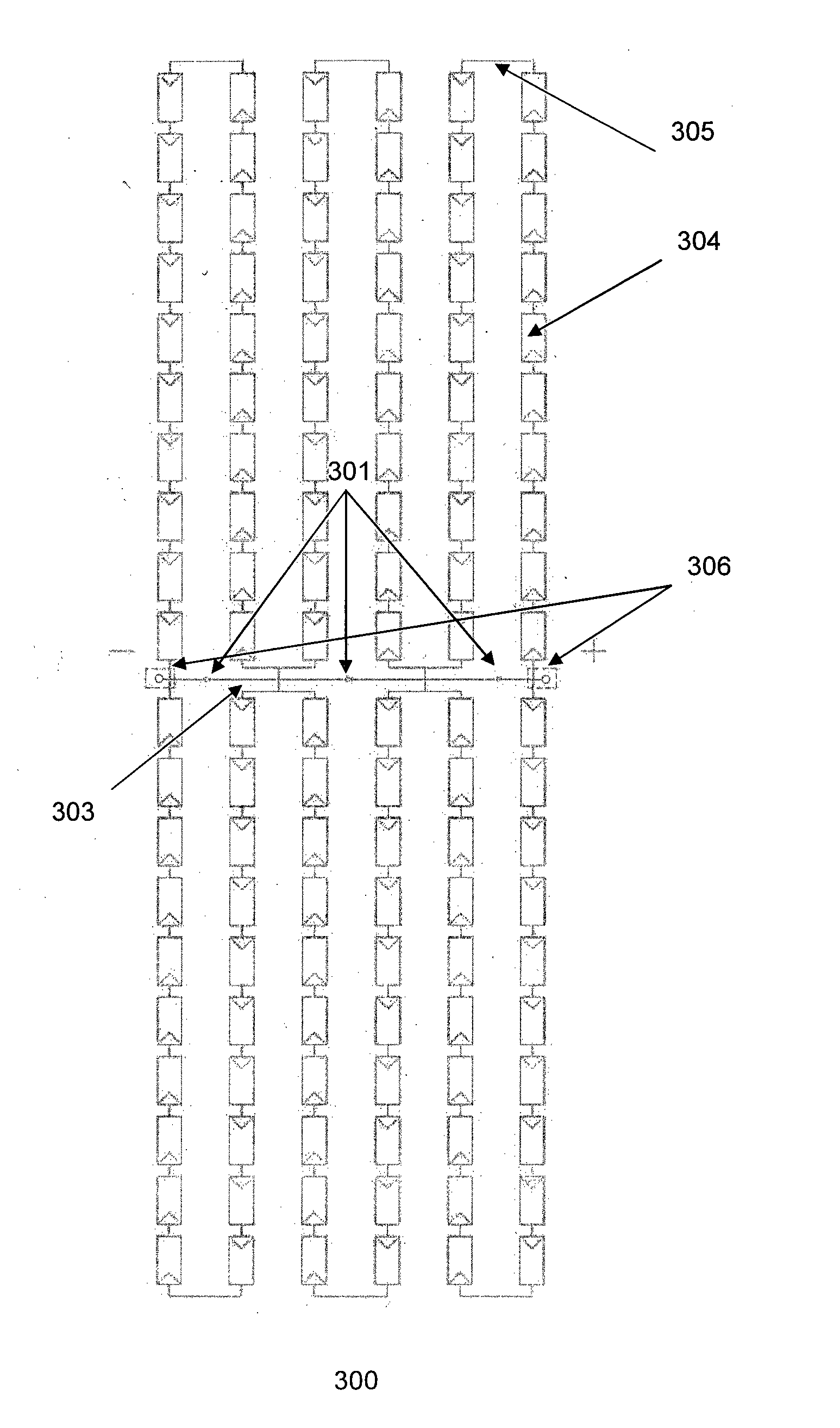
[0022]FIG. 2a shows an embodiment of a solar cell assembly layout 200 and FIG. 2b shows a corresponding electrical schematic diagram. In one embodiment, the solar cell assembly is a solar cell module. In another embodiment, the solar cell assembly is a portion of a solar cell module. The solar cell assembly may include solar cells 204 which may be arranged in one or more solar cell units. As illustrated in FIG. 2a, the solar cell assembly 200 includes three solar cell units, for example, a first solar cell unit 211, a second solar cell unit 212 and a third solar cell unit 213. Having solar cell assemblies including another number of solar cell units may also be useful.

[0023]In one embodiment, a solar cell unit includes a first solar cell s...


PUM


Abstract

A solar cell assembly (200) is presented. The solar cell assembly includes one or more solar cell units (211) coupled in series. The solar cell unit includes a first solar cell series (221) and a second solar cell series (222) connected in parallel. The first and second solar cell series include a plurality of cells (202) connecting in series respectively. The solar cell assembly also includes a by-pass diode (201) coupled to each solar cell unit and shared between the first and second solar cell series in each solar cell unit.

Description

FIELD OF THE INVENTION[0001]The present invention relates to solar cell assemblies and to solar cell modules including such solar cell assemblies.TECHNICAL BACKGROUND[0002]Solar cells are used to convert sunlight into electricity using a photovoltaic effect. As shown in FIG. 1a, solar cell modules 100 on the basis of crystalline silicon solar cells may typically include 6×10 solar cells 104 of dimensions 15.6×15.6 cm2 which may be arranged in six parallel interconnected solar cell strings. Each string may include ten or twelve mono- or multi-crystalline solar cells that are connected in series by copper ribbons 106. The strings in turn may be again connected in series by so-called cross-connectors 105 so that all cells in the module are connected in series. Solar cell modules with for example 4×9, 6×8 or 6×12 solar cells in the same type of configuration are also common.[0003]Under normal operation conditions, all solar cells may be illuminated and operate at their maximum power poi...

Claims


Application Information

Patent Timeline
IPC IPC(8): H01L31/0443H02S40/34H01L31/05
CPCH01L31/0443H02S40/34H01L31/0504H01L31/044H02J1/108H02J2300/24H02J3/381Y02E10/56H02J3/466Y02E10/50H02J3/383H02J3/38B23H7/02B23H7/20G05B19/4155G05B2219/45221
Inventor SRIDHARA, SHANKAR GAURIDIESTA, NOEL G.ROSTAN, PHILIPP JOHANNESWADE, ROBERT
Owner REC SOLAR
Why Eureka
Try Eureka