
Method and device for designing electrical circuit

a technology for electrical circuits and circuits, applied in the direction of design optimisation/simulation, instruments, computing, etc., can solve the problems of significant affecting the performance of electrical devices and significant affecting the efficiency of design and development of electrical devices

Inactive Publication Date: 2016-05-19
SEMICON MFG INT (SHANGHAI) CORP
View PDF32 Cites 8 Cited by
  • Summary
  • Abstract
  • Description
  • Claims
  • Application Information

AI Technical Summary

Benefits of technology

The patent invention allows for the inclusion of layout-dependent effect parameter values in electrical circuit simulations at an early stage in the design process. This helps to minimize discrepancies between the layout model and the schematic model, reducing the need for repetitive circuit simulations and model revisions. As a result, the design process becomes more efficient, with satisfactory results being achieved.

Problems solved by technology

In the manufacturing and / or operation of an electrical device, such as a complementary metal-oxide-semiconductor (CMOS) device, various layout-dependent effects may significantly affect characteristics (e.g., carrier mobility, threshold voltage, etc.) of the electrical device and therefore may significant affect the performance of the electrical device.
Time and work required for the iterations may significantly affect the efficiency of the design and development of the electrical device.

Method used


Image

  • Method and device for designing electrical circuit
  • Method and device for designing electrical circuit
  • Method and device for designing electrical circuit

Examples


Embodiment Construction

[0036]Example embodiments of the present invention are described with reference to the accompanying drawings. As those skilled in the art would realize, the described embodiments may be modified in various different ways, all without departing from the spirit or scope of the present invention. Embodiments of the present invention may be practiced without some or all of these specific details. Well known process steps and / or structures may not have been described in detail in order to not unnecessarily obscure the present invention.

[0037]The drawings and description are illustrative and not restrictive. Like reference numerals may designate like (e.g., analogous or identical) elements in the specification. Repetition of description may be avoided.

[0038]The relative sizes and thicknesses of elements shown in the drawings are for facilitate description and understanding, without limiting the present invention. In the drawings, the thicknesses of some layers, films, panels, regions, etc...


PUM


Abstract

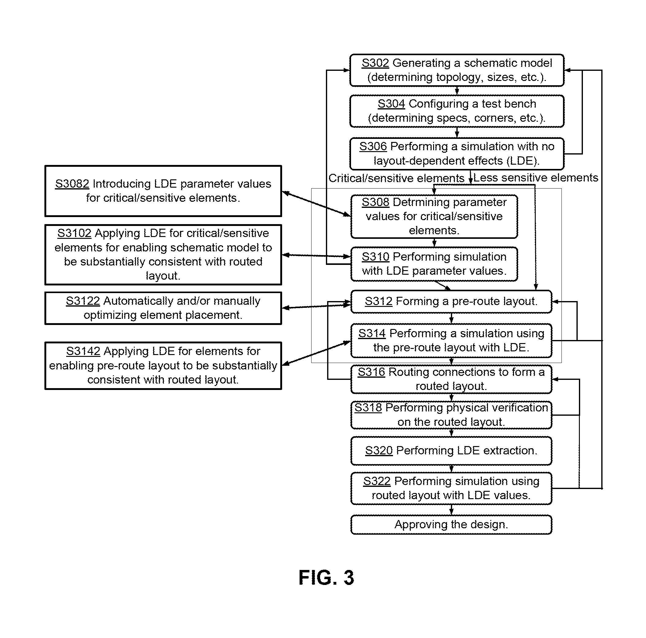
A method may be used for designing an electrical circuit. The method may be implemented using a device that includes hardware. The method may include the following steps: generating a schematic model that represents the electrical circuit; placing representations of a set of elements of the electrical circuit for forming a pre-route layout model; and using the pre-route layout model and a set of layout-dependent effect parameter values to perform a pre-route simulation. The set of layout-dependent effect parameter values may pertain to the set of elements of the electrical circuit.

Description

CROSS-REFERENCE TO RELATED APPLICATION[0001]This application claims priority to and benefit of Chinese Patent Application No. 201410640866.9, filed on 13 Nov. 2014. The Chinese Patent Application is incorporated herein by reference in its entirety.BACKGROUND OF THE INVENTION[0002]The present invention is related to a method and a device that may be used for designing an electrical circuit. The electrical circuit may be included in an electrical device, such as a semiconductor device.[0003]In the manufacturing and / or operation of an electrical device, such as a complementary metal-oxide-semiconductor (CMOS) device, various layout-dependent effects may significantly affect characteristics (e.g., carrier mobility, threshold voltage, etc.) of the electrical device and therefore may significant affect the performance of the electrical device. The layout-dependent effects may be related to physical phenomena associated with arrangement of elements and adjacent elements in the electrical c...

Claims


Application Information

Patent Timeline
Patent Type & Authority Applications(United States)
IPC IPC(8): G06F17/50
CPCG06F17/5072G06F17/5009G06F17/5077G06F30/392G06F30/394G06F30/20G06F30/398
Inventor ZHU, GUANGCHEN, XIANMINFENG, GUANG TAOYANG, CHIA CHI
Owner SEMICON MFG INT (SHANGHAI) CORP
Learn More