
Aerial system and vehicle for continuous operation

a technology of continuous operation and aerial system, which is applied in the direction of arrester hooks, process and machine control, instruments, etc., can solve the problems of insufficient self-sufficient existing uavs and uav systems in at least two respects, requiring routine maintenance, and requiring both autonomous capture and release of the vehicl

Active Publication Date: 2016-05-19
AURORA FLIGHT SCI CORP
View PDF7 Cites 304 Cited by
  • Summary
  • Abstract
  • Description
  • Claims
  • Application Information

AI Technical Summary

Benefits of technology

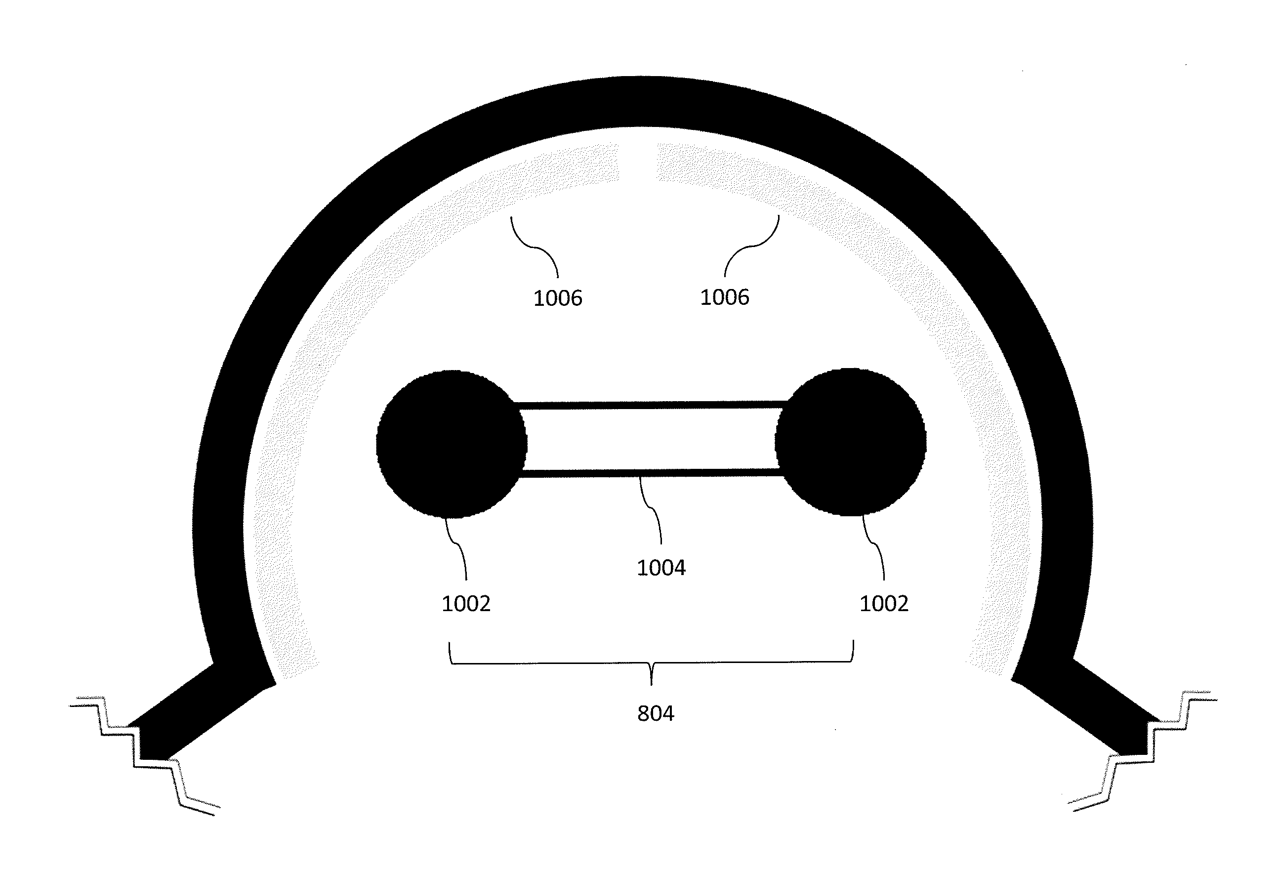
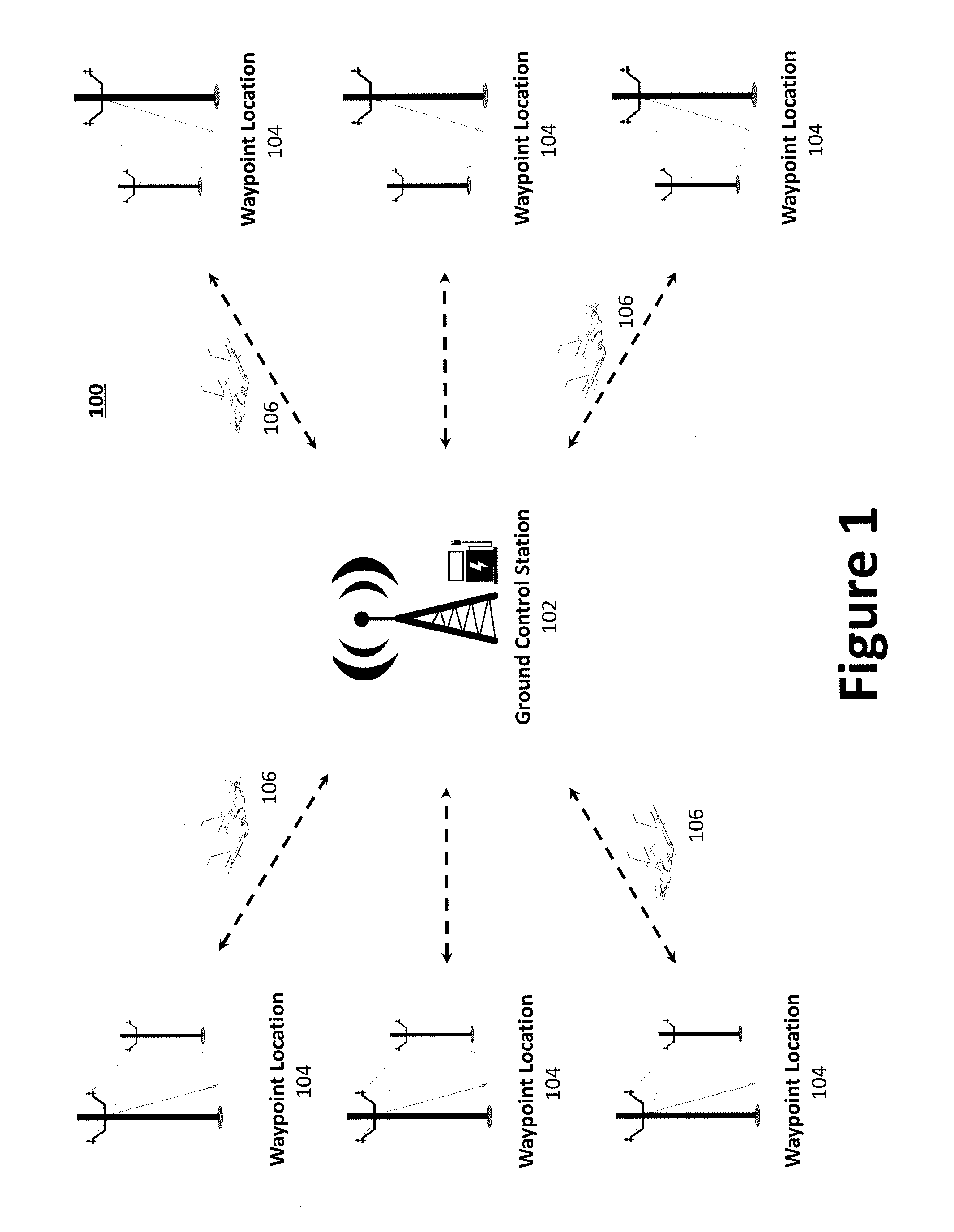
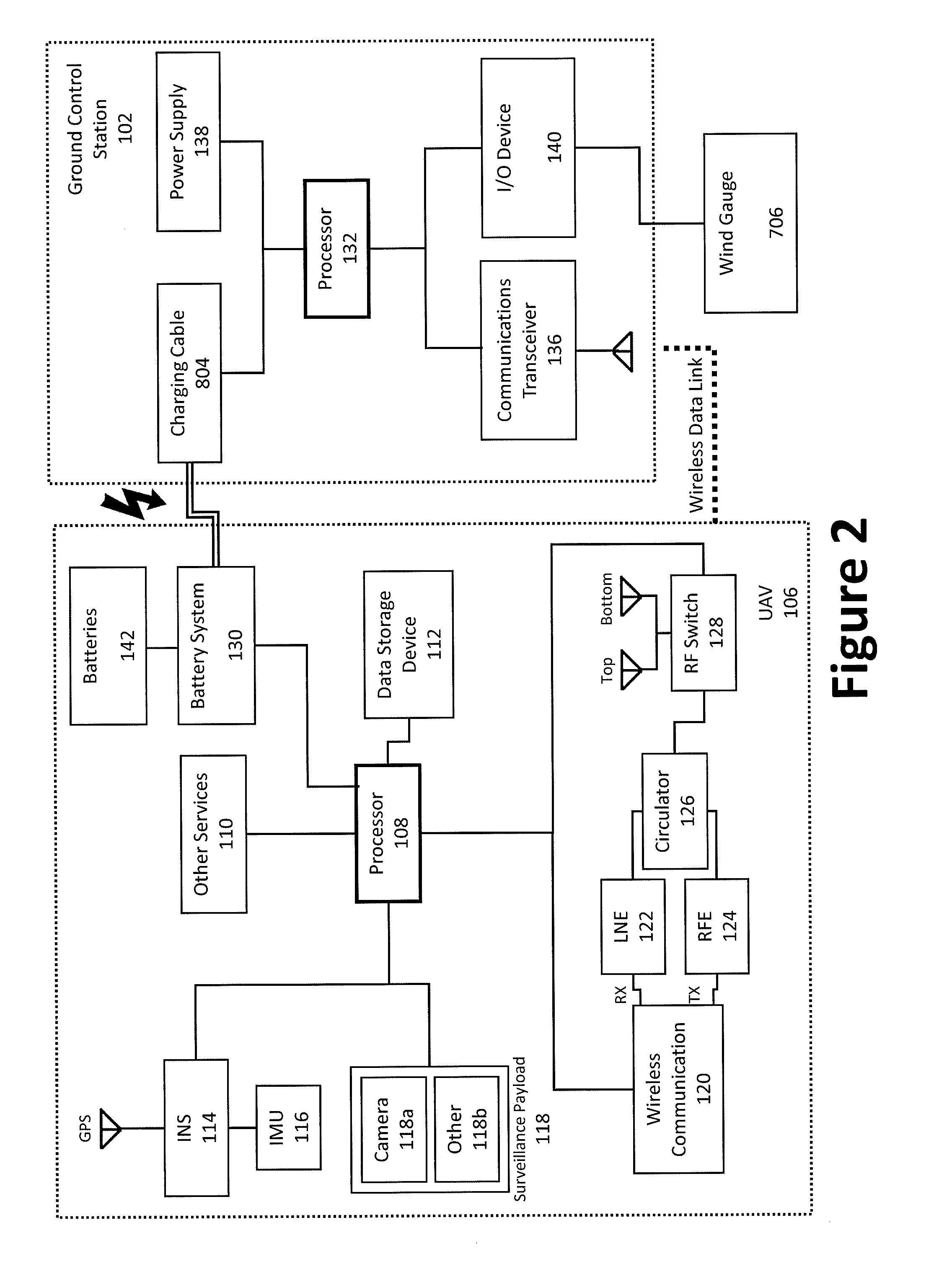
The present patent aims to provide a system and method for operating an autonomous self-charging aerial vehicle surveillance system. The system includes an aerial vehicle equipped with a sensor payload for generating surveillance data, a waypoint location with an arresting cable, and a ground control station with a charging cable. The aerial vehicle is configured to autonomously travel between the waypoint location and the ground control station and to connect and disconnect with the arresting cable and charging cable using a capturing hook. The system also includes a camera and infrared reflectors for accurately navigating the aerial vehicle. The technical effects of the patent text offer improved efficiency and accuracy in surveillance and navigation of aerial vehicles.

Problems solved by technology

While a number of UAVs and UAV systems are disclosed through the above references, existing UAVs and UAV systems are deficient in at least two respects.
First, existing UAVs are not entirely self-sufficient and require routine upkeep, such as charging and / or refueling.
Second, existing UAVs are generally concerned only with the cable capture (e.g., landing), but do not consider both the autonomous capture and release of the vehicle.

Method used


Image

  • Aerial system and vehicle for continuous operation
  • Aerial system and vehicle for continuous operation
  • Aerial system and vehicle for continuous operation

Examples


Embodiment Construction

[0023]Embodiments of the present invention will be described hereinbelow with reference to the accompanying drawings. In the following description, well-known functions or constructions are not described in detail because they would obscure the invention in unnecessary detail. For this application, the following terms and definitions shall apply:

[0024]The terms “communicate” and “communicating,” as used herein, refer to both transmitting, or otherwise conveying, data from a source to a destination and delivering data to a communications medium, system, channel, network, device, wire, cable, fiber, circuit, and / or link to be conveyed to a destination.

[0025]The term “computer,” as used herein, refers to a programmable device designed to sequentially and automatically carry out a sequence of arithmetic or logical operations, including without limitation, personal computers (e.g., those available from Gateway, Hewlett-Packard, IBM, Sony, Toshiba, Dell, Apple, Cisco, Sun, etc.), handheld...


PUM


Abstract

An aerial vehicle system for gathering data may comprise a Waypoint Location, wherein the Waypoint Location comprises an arresting cable; a Ground Control Station, wherein the Ground Control Station comprises a charging cable; and an aerial vehicle, wherein the aerial vehicle comprises an onboard battery, a capturing hook and a sensor payload for generating surveillance data. The aerial vehicle may be configured to autonomously travel between the Waypoint Location and the Ground Control Station. The aerial vehicle may be configured to couple with the arresting cable via the capturing hook. The aerial vehicle may be configured to electronically couple with the charging cable via the capturing hook to facilitate charging the aerial vehicle's onboard battery.

Description

CROSS-REFERENCE TO RELATED APPLICATIONS[0001]This application claims priority to U.S. Provisional Patent Application No. 61 / 851,866, filed on Mar. 14, 2013, entitled Aerial System and Vehicle for Continuous Operation,” which is hereby incorporated by reference.TECHNICAL FIELD[0002]The present invention relates to systems and methods for use with Unmanned Aerial Vehicles (“UAVs”) and Unmanned Aerial Systems (“UASs”). More specifically, the present invention relates to systems and methods for enabling the operation of an autonomous, self-charging aerial vehicle surveillance system.BACKGROUND INFORMATION[0003]The use of Unmanned Aerial vehicles (“UAVs”) and Small Unmanned Aerial Systems (“SUASs”) has grown in recent years and such UAVs and SUASs are employed in a wide variety of applications, including both military and civilian uses. In some applications, a UAV or SUAS may be required to maneuver quickly, or in tight spaces, over a wide range of speeds. Accordingly, several efforts ha...

Claims


Application Information

Patent Timeline
IPC IPC(8): B64F1/02B64C39/02B60L11/18B64D45/08G05D1/10B64C25/68B64D47/08
CPCB64F1/02B64C25/68B64C39/024B64D47/08B64C2201/182G05D1/101B60L11/1816B64C2201/042B64C2201/141B64D45/08B60L2200/10Y02T90/16Y02T10/7072Y02T90/14B60L53/14B60L53/68Y02T10/70Y02T90/12B64F1/029B64U10/25B64U50/34B64U50/19B64U2101/30B64U2201/10B64U70/30B64F1/362B64D47/04
Inventor PEVERILL, JAMESWOODWORTH, ADAMFREUDBERG, BENJAMINCOTTRELL, DANMCKENNA, TERRENCE
Owner AURORA FLIGHT SCI CORP
Learn More