
Stock ejector assembly

Active Publication Date: 2016-05-12
STANDARD LIFTERS INC
View PDF0 Cites 5 Cited by
  • Summary
  • Abstract
  • Description
  • Claims
  • Application Information

AI Technical Summary

Benefits of technology

The present invention is a stock ejector assembly that uses a large spring which results in a longer product life. The spring is on the outside of the assembly which allows for a larger spring to be used while keeping the overall size of the assembly small. Additionally, the assembly has an increased surface area that comes into contact with the stock, preventing the stock from being marked or sticking to the ejector.

Problems solved by technology

Current die making processes require carefully machined precision holes and recesses in the die set for mounting the individual components, such that the same are quite labor intensive and require substantial lead time to make, test, and set up in a stamping press.
Consequently, such metal forming dies are very expensive to design, manufacture, and repair or modify.
When a liquid is used on the stock or upper and / or lower die parts of a metal forming die, the stock has a tendency to stick to the die parts.
This is a self-contained assembly that includes a very small diameter spring which is prone to fail quickly due to its size.
When the threaded spring plunger fails, it is a hassle for stampers as they have to continuously replace the threaded spring plungers.
Another problem is that the threaded spring plungers typically have a pointed tip that can leave a mark on the stock if the spring pressure is too great.
Such spring plungers 140 typically fail due to the small spring, which effects the overall lifespan of the spring plunger.
In addition, the components of the ejector pin assemblies 148 are small components and require an immense amount of time to assemble.
The need for an improved stock ejector thus stems from the issues that metal stamping producers and die shops have long had when creating an “oil breaker” setup in their dies.
The improved stock ejector addresses two main items that are currently problematic: The first is that it utilizes a large spring, which provides a much longer product life than a traditional spring plunger.
This provides very little contact with the stock and it can leave a “mark” if the spring pressure compared to the contact surface area on the stock are not proper.

Method used


Image

  • Stock ejector assembly
  • Stock ejector assembly
  • Stock ejector assembly

Examples


Embodiment Construction

[0034]For purposes of description herein, the terms “upper,”“lower,”“right,”“left,”“rear,”“front,”“vertical,”“horizontal,” and derivatives thereof shall relate to the invention as oriented in the attached drawings. However, it is to be understood that the invention may assume various alternative orientations and step sequences, except where expressly specified to the contrary. It is also to be understood that the specific devices and processes illustrated in FIGS. 1-14, and described in the following specification, are simply exemplary embodiments of the inventive concepts defined in the appended claims. Hence, specific dimensions and other physical characteristics relating to the embodiments disclosed herein are not to be considered as limiting, unless the claims expressly state otherwise.

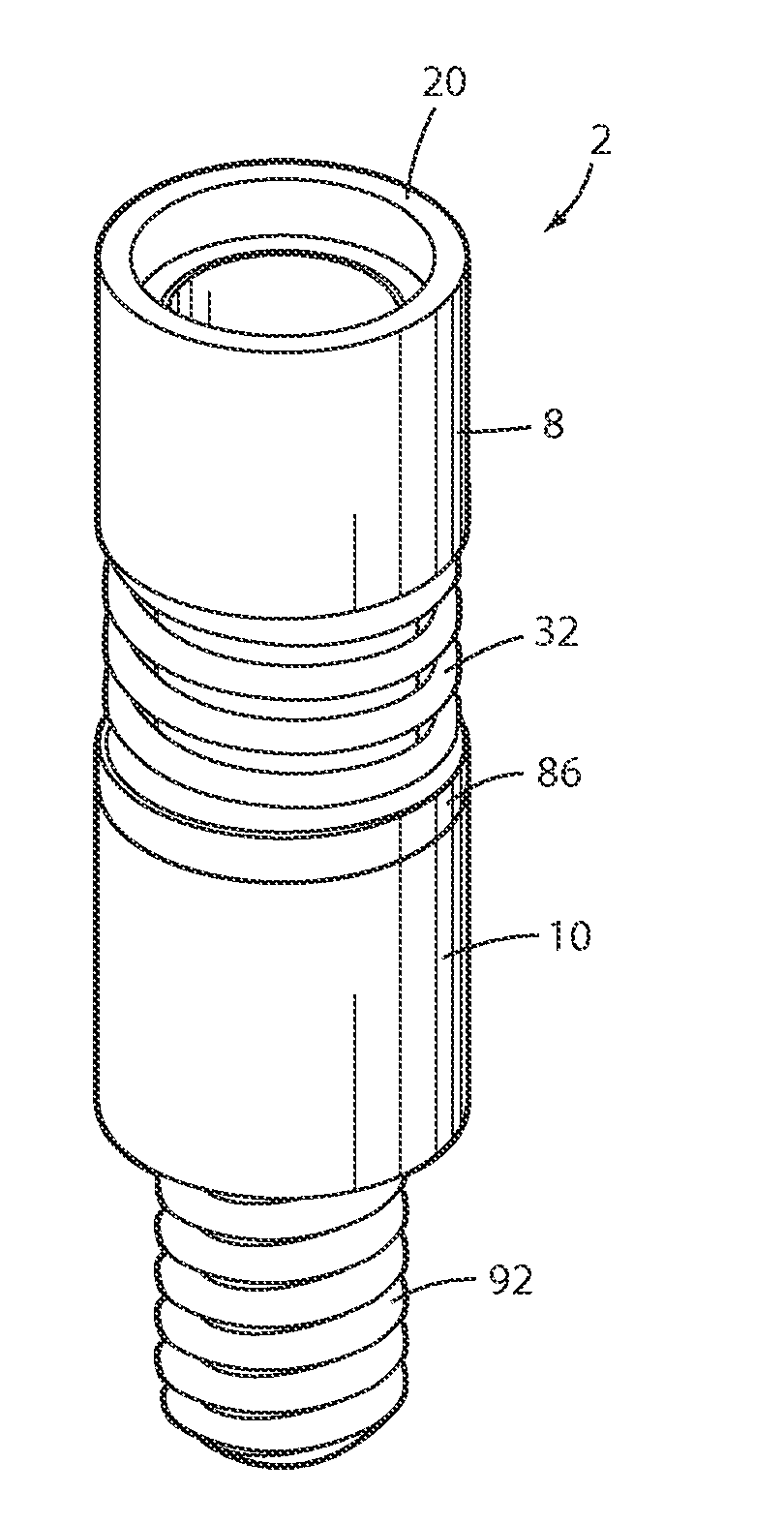
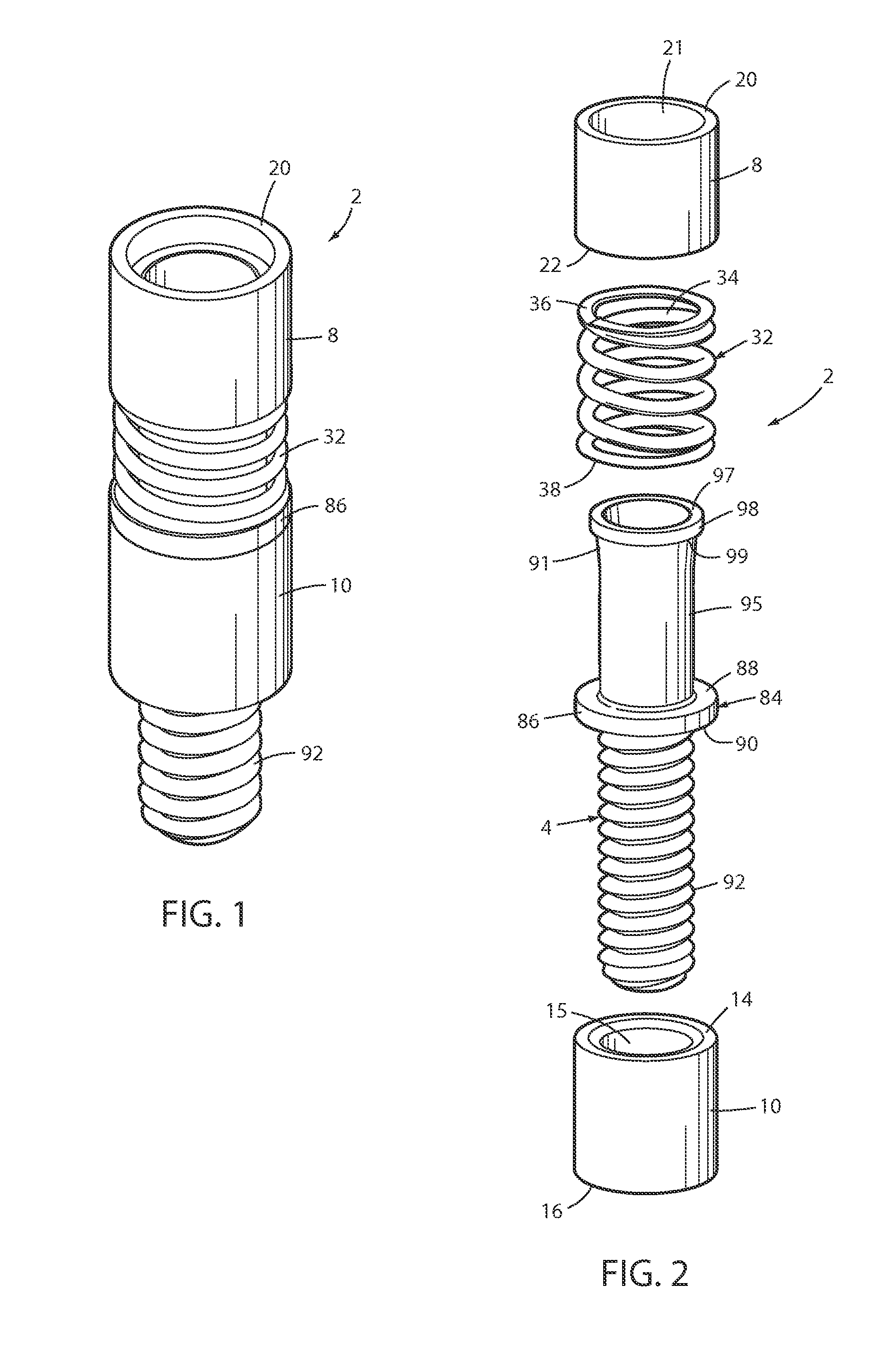
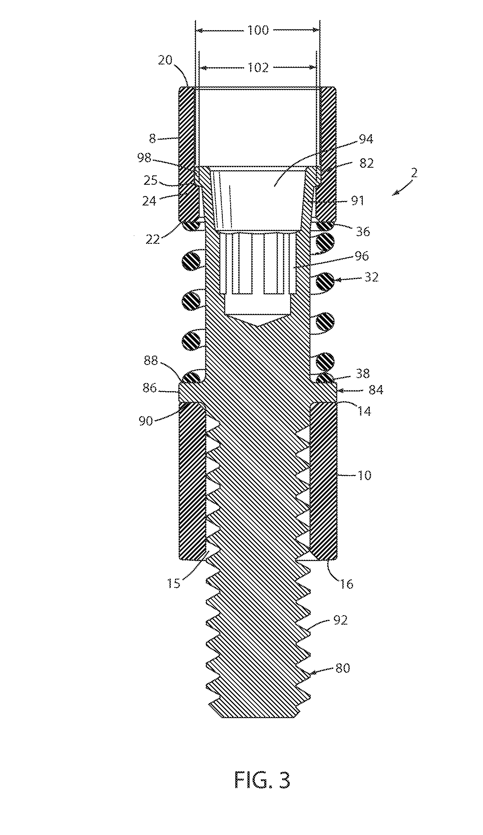
[0035]The reference numeral 2 (FIGS. 1-14) generally designates a stock ejector assembly embodying an aspect of the present invention. As shown in FIGS. 11-14, the stock ejector assembly 2 is part...


PUM

PropertyMeasurementUnit
Pressureaaaaaaaaaa
Adhesion strengthaaaaaaaaaa
Surface areaaaaaaaaaaa

Abstract

A stock ejector assembly and method for metal forming dies includes a stock ejector with a large spring and a ring-style stripper. The ring-style stripper provides a larger surface area for contacting the stock. The large compression spring is preloaded and when a load is applied, the stripper retracts and the spring pressure increases. When the dies separate, the stock ejector pushes the part off flat surfaces, separating surfaces sealed by adhesion, including, but not limited to, oil or lubricant adhesion.

Description

CROSS REFERENCE TO RELATED APPLICATION[0001]Applicants hereby claim the priority benefits under the provisions of 35 U.S.C. §119, basing said claim of priority on related U.S. Provisional Application No. 62 / 075,966 filed Nov. 6, 2014.BACKGROUND OF THE INVENTION[0002]The present invention relates to metal forming dies and the like, and in particular to a stock ejector assembly and associated method incorporating a unique stock ejector assembly.[0003]Metal forming dies, such as stamping dies and the like, are well known in the art.[0004]Progressive metal forming dies are unique, very sophisticated mechanisms which have multiple stations or progressions that are aligned longitudinally, and are designed to perform a specified operation at each station in a predetermined sequence to create a finished metal part. Progressive stamping dies are capable of forming complex metal parts at very high speeds, so as to minimize manufacturing costs.[0005]Heretofore, the dies used in metal forming p...

Claims


Application Information

Patent Timeline
IPC IPC(8): B21D37/08B23P15/24
CPCB23P15/24B21D37/08B21D45/02
Inventor BREEN, SCOTT M.PYPER, JOEL T.
Owner STANDARD LIFTERS INC
Learn More