Surgical navigation system with one or more body borne components and method therefor

a surgical navigation system and body-borne technology, applied in the field of computer assisted surgery and surgical navigation systems, can solve the problems of binocular-based navigation systems, large and expensive medical equipment systems, and disruption of line-of-sight between cameras and objects

Inactive Publication Date: 2016-05-12
INTELLIJOINT SURGICAL
View PDF4 Cites 11 Cited by
  • Summary
  • Abstract
  • Description
  • Claims
  • Application Information

AI Technical Summary

Benefits of technology

The patent describes a system and method for performing a navigated surgery using a sensor and an intra-operative computing unit (ICU). The sensor detects targets attached to a patient at a surgical site and the ICU calculates the relative position of these targets. The system can provide display information to a user through a heads-up display or other display unit, and can also receive user input through the sensor. The technical effects of this system include improved precision in surgery and reduced risk of complications.

Problems solved by technology

The binocular cameras are part of large and expensive medical equipment systems.
There are several limitations to existing binocular-based navigation systems, including line-of-sight disruptions between the cameras and the objects, ability to control computer navigation software, cost, and complexity.

Method used


Image

  • Surgical navigation system with one or more body borne components and method therefor
  • Surgical navigation system with one or more body borne components and method therefor
  • Surgical navigation system with one or more body borne components and method therefor

Examples


camera embodiment

Handheld Camera Embodiment

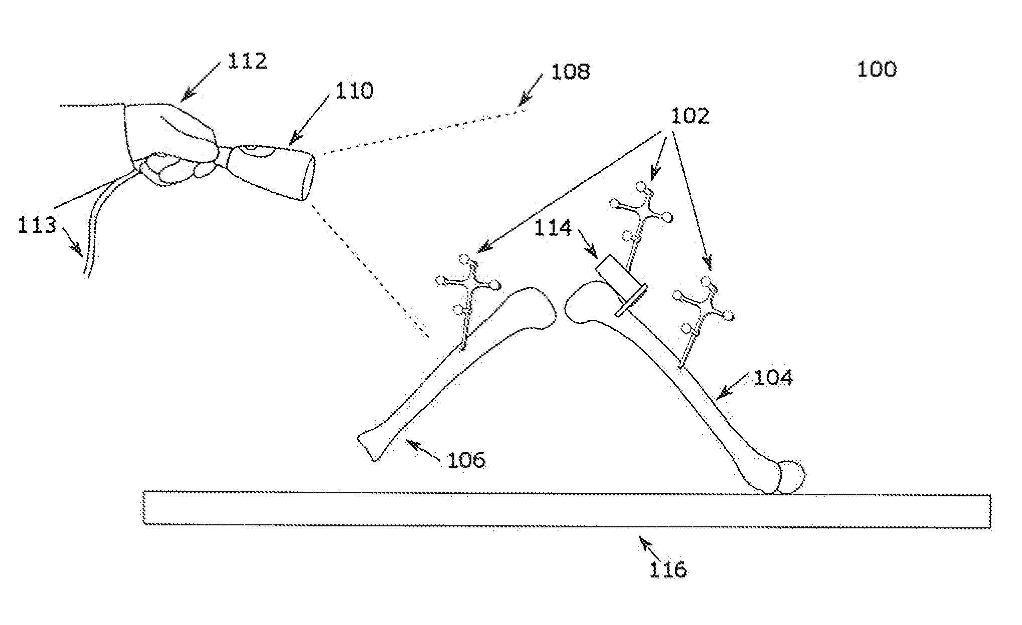
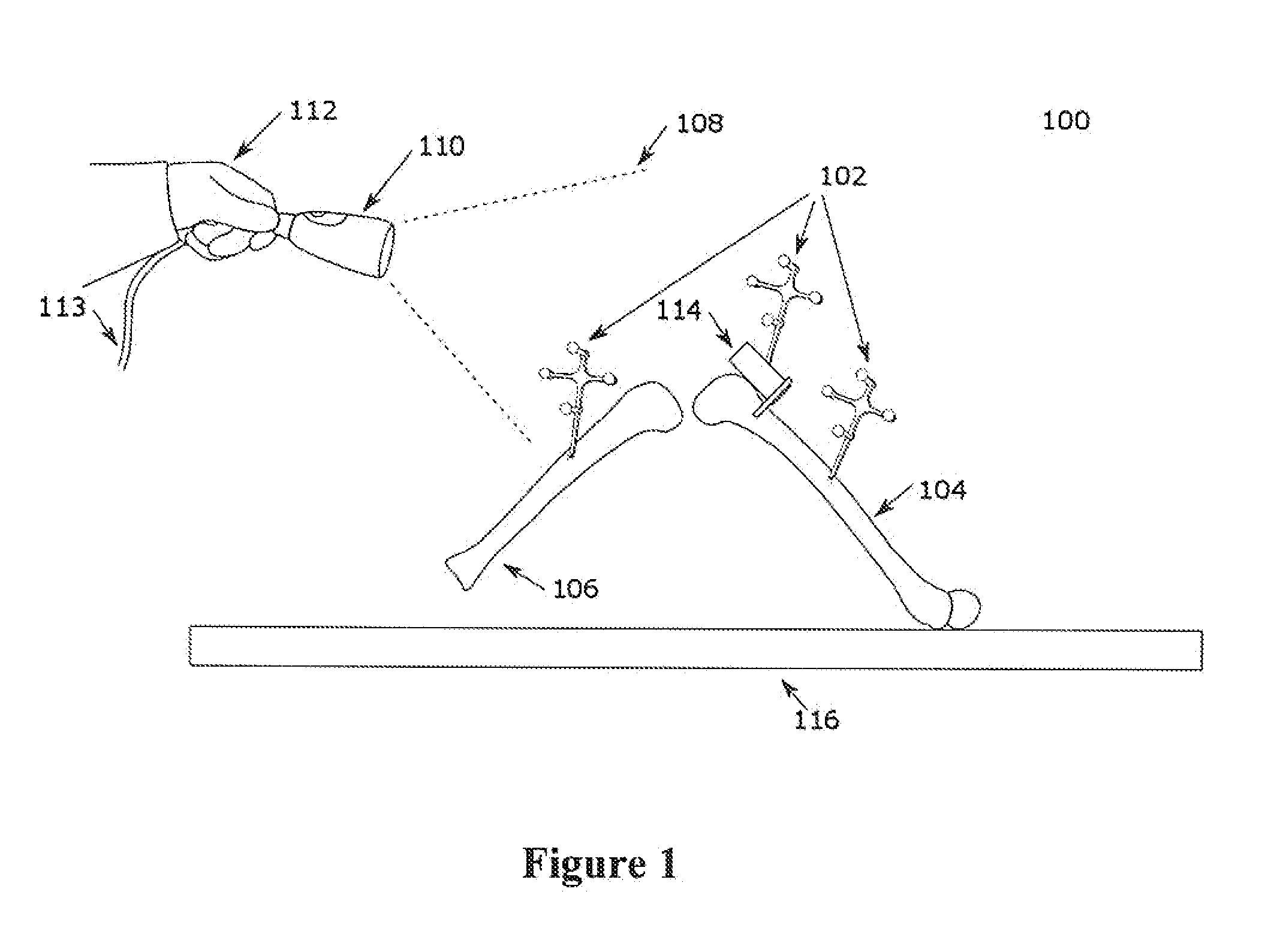
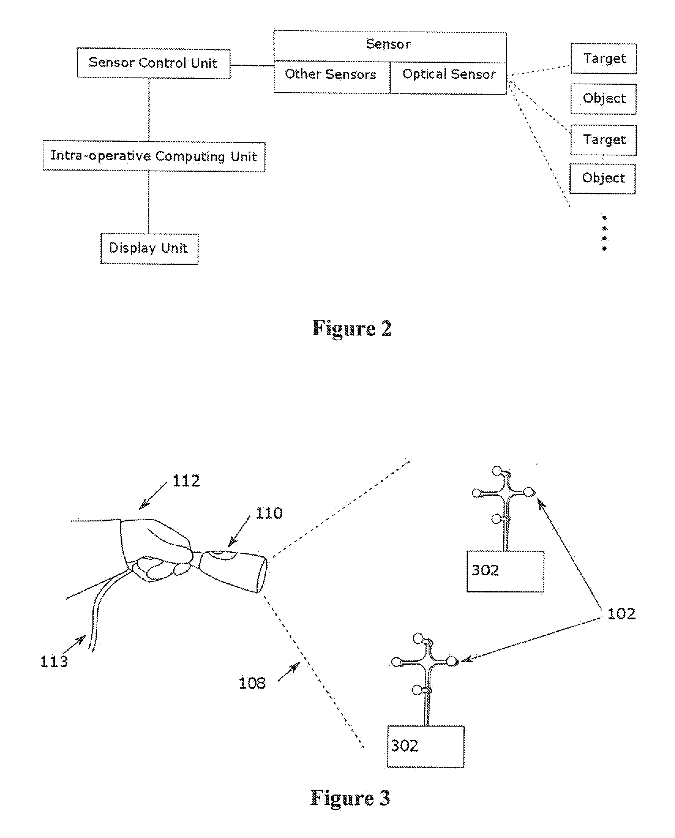
[0052]In one embodiment, a sensor is configured for handheld use. As depicted in FIG. 3, the sensor 110 may localize two or more targets 102, in order to compute a relative pose between the targets 102. The targets 102 are attached to objects 302 and the relative pose between the objects 302 can also be calculated. In relation to navigated TKA, the objects could be the femur 104 and the tibia 106, or the femur 104 and the cutting guide 114.

[0053]Furthermore, both handheld and non-handheld modes may be supported for use of the sensor within the same surgery. This is illustrated in FIG. 4a and FIG. 4b. For example, during a TKA, it may be preferable to leave the sensor 110 mounted to a fixed structure 402 for the majority of the procedure with the use of a releasable mechanical connection 404, such as the one described in U.S. 20140275940 titled “System and method for intra-operative leg position measurement”, the entire contents of which are incorporated her...

embodiment

Body Mounted Embodiment

[0055]As illustrated in FIG. 5, in addition to handheld configurations, the sensor 110 may be mounted onto a surgeon 502 for other user) using a sensor mounting structure 504. The sensor mounting structure 504 may allow the sensor to be attached to a surgeon's forehead (by way of example, shown as a headband). The sensor 110 is preferably placed on the sensor mounting structure 504 such that the working volume 408 of the sensor 110 and the surgeon's visual field of view 506 are substantially aligned, i.e. the majority of the working volume 408 overlaps with the field of view 108 of the sensor 110. In such a configuration, if the surgeon 502 can see the targets 102, the sensor 110 (while mounted on the sensor mounting structure 504) will likely be able to do so as well. This configuration allows the surgeon to rapidly and intuitively overcome line-of-sight disruptions between the sensor 110 and the targets 102. In this configuration, it is desirable that the op...


PUM


Abstract

A system for performing a navigated surgery comprises a first target attached to a patient at a surgical site and a second target at the surgical site. An optical sensor is coupled to the user and detects the first target and second target simultaneously in a working volume of the sensor. An intra-operative computing unit (ICU) receives sensor data concerning the first target and second target, calculates a relative pose and provides display information. The sensor can be handheld, body-mounted or head-mounted, and communicate wirelessly with the ICU. The sensor may also be mountable on a fixed structure (e.g. proximate) and in alignment with the surgical site. The ICU may receive user input via the sensor, where the user input is at least one of sensor motions, voice commands, and gestures presented to the optical sensor by the user. The display information may be presented via a (heads-up) display unit.

Description

CROSS REFERENCE TO RELATED APPLICATIONS[0001]This application claims priority to U.S. provisional application No. 62 / 072,041 titled “Systems, Methods and Devices for Anatomical Registration and Surgical Localization” and filed on Oct. 29, 2014, the entire contents of which are incorporated herein by reference.[0002]This application claims priority to U.S. provisional application No 62 / 072,030 titled “Devices including a surgical navigation camera and systems and methods for surgical navigation” and filed on Oct. 29, 2014, the entire contents of which are incorporated herein by reference.[0003]This application claims priority to U.S. provisional application No. 62 / 084,891 titled “Devices, systems and methods for natural feature tracking of surgical tools and other objects” and filed on Nov. 26, 2014, the entire contents of which air incorporated herein by reference.[0004]This application claims priority to U.S. provisional application No. 62 / 072,032 titled “Devices, systems and metho...

Claims


Application Information

Patent Timeline
IPC IPC(8): G06F19/00
CPCA61B19/5244A61B2019/5255A61B2560/0493A61B2019/262A61B2017/00207A61B2019/5272A61B2090/3983A61B2034/2057A61B2034/2068A61B2034/2048A61B34/20A61B2034/2055A61B2034/2072A61B2090/067A61B46/10A61B2090/061A61B2090/064A61B5/6847A61B2034/2065A61B90/30A61B90/361A61B2090/364A61B2090/373A61B2090/3937A61B17/1703A61B34/10A61B2034/105A61B90/06G06T7/74G06T7/337G06T2207/30008
Inventor HLADIO, ANDRE NOVOMIRBAKIRTZIAN, ARMEN GAROFANSON, RICHARD TYLER
Owner INTELLIJOINT SURGICAL
Why Eureka
Try Eureka