
Gear mechanism used for slide rail

a technology of gear mechanism and slide rail, which is applied in the direction of friction gearing, toothed gearing, gearing, etc., can solve the problems of damage to gears and racks, and achieve the effects of simple and reasonable structure, reliable performance, and simple assembly

Inactive Publication Date: 2016-05-12
GUANGDONG TAIMING METAL PROD
View PDF2 Cites 10 Cited by
  • Summary
  • Abstract
  • Description
  • Claims
  • Application Information

AI Technical Summary

Benefits of technology

The present invention provides a gear mechanism for slide rails that has a simple and reasonable structure, easy assembly, reliable performance and long service life. The gear mechanism comprises two gears-A gear and B gear-which are closely coordinated and assembled through polygonal column and polygonal hole. When the acting force is greater than a certain value, the polygonal hole is expanded and two gears make relative slipping rotation. When the acting force is greater than a certain value, two gears make synchronous rotation. This change ensures that two gears and upper / lower gears are mutually engaged at correct positions to adapt the needs of the slide rail at different stages and effective protect the gears and racks. The invention achieves smoother closing / opening of the drawer.

Problems solved by technology

However, the movable rail is not synchronous with the middle rail, so that it is easy to cause damage to the gears and racks.

Method used


Image

  • Gear mechanism used for slide rail
  • Gear mechanism used for slide rail
  • Gear mechanism used for slide rail

Examples


Embodiment Construction

[0020]Further detailed description of the present invention is provided with reference to specific embodiments in combination with attached drawings.

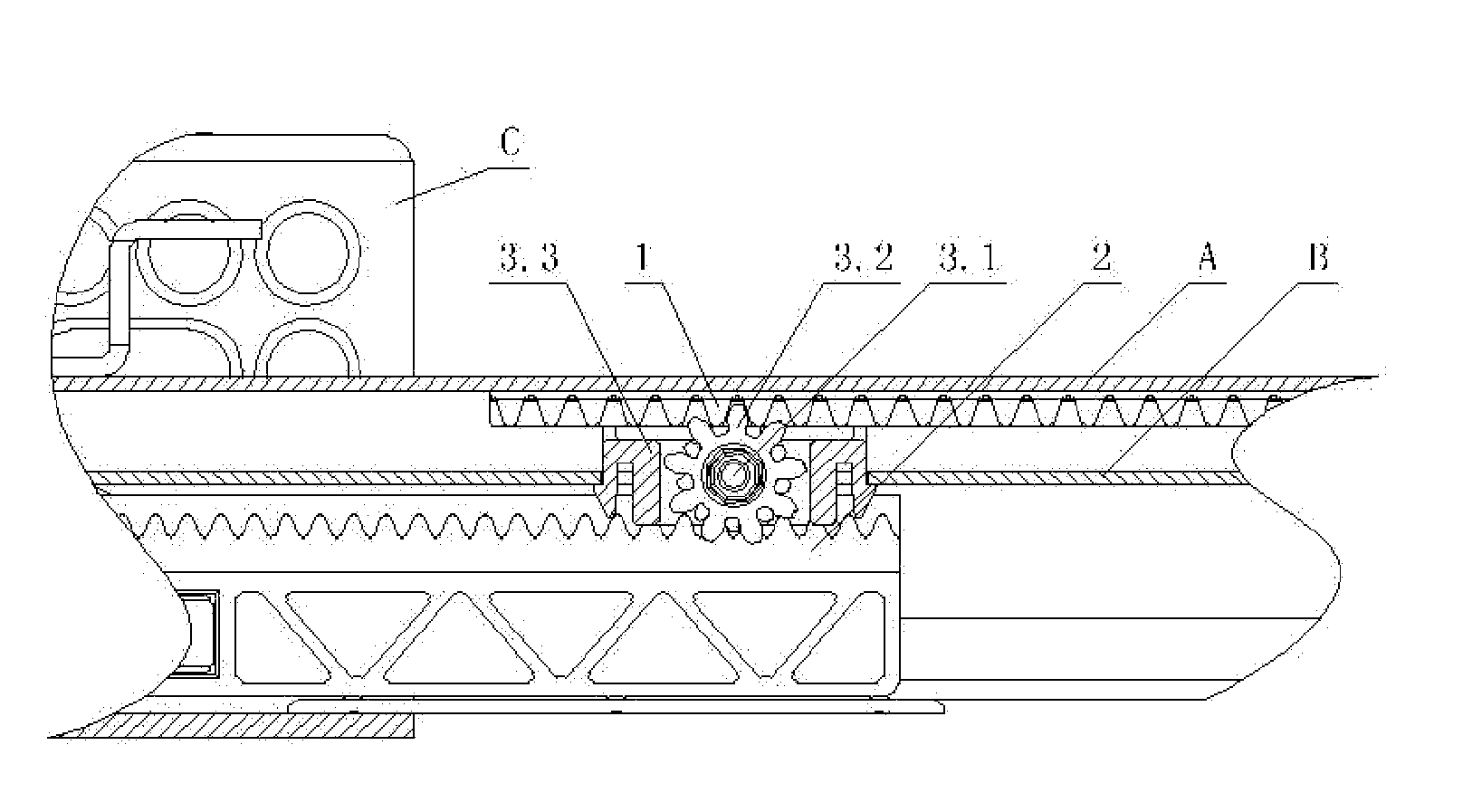
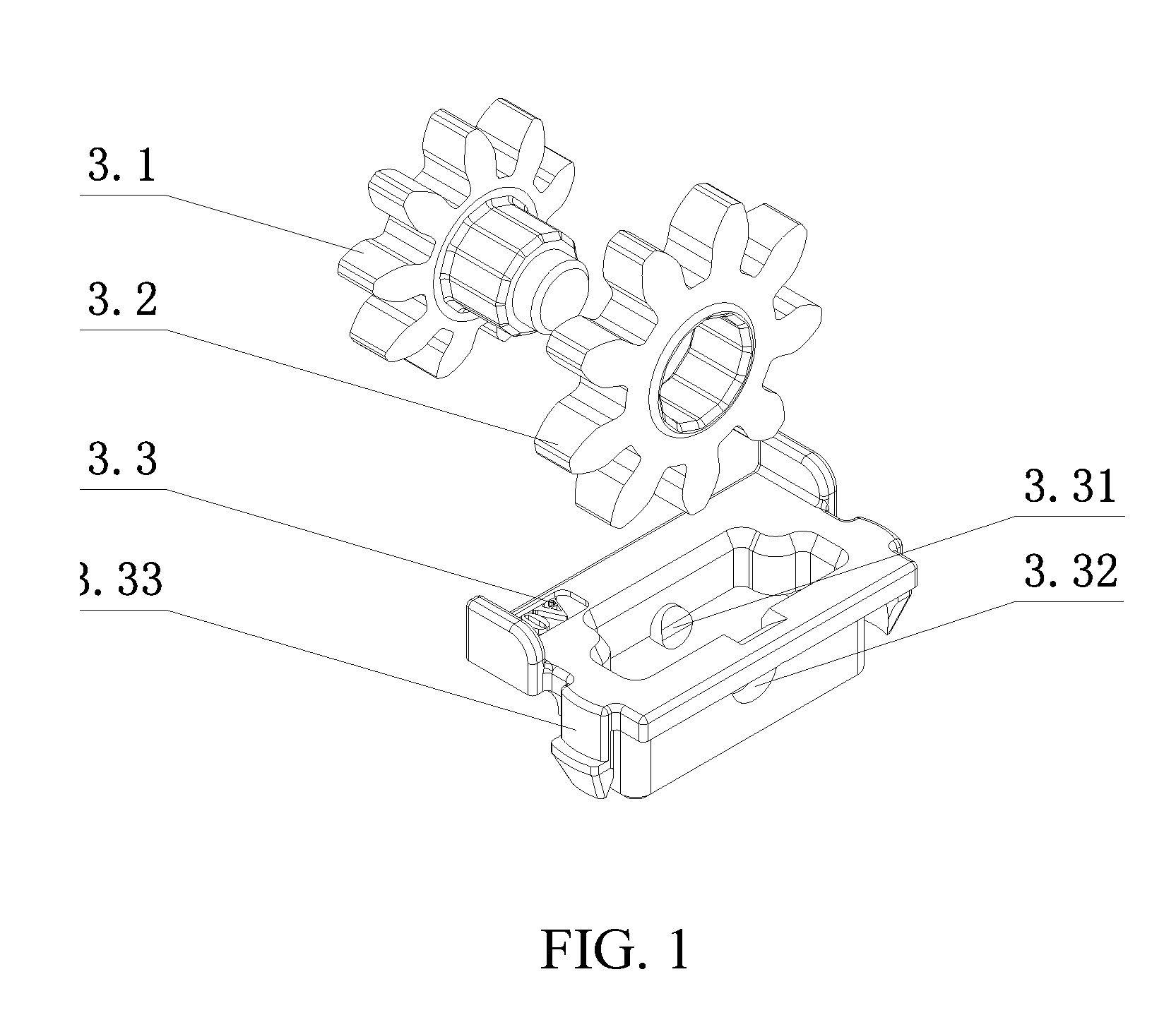
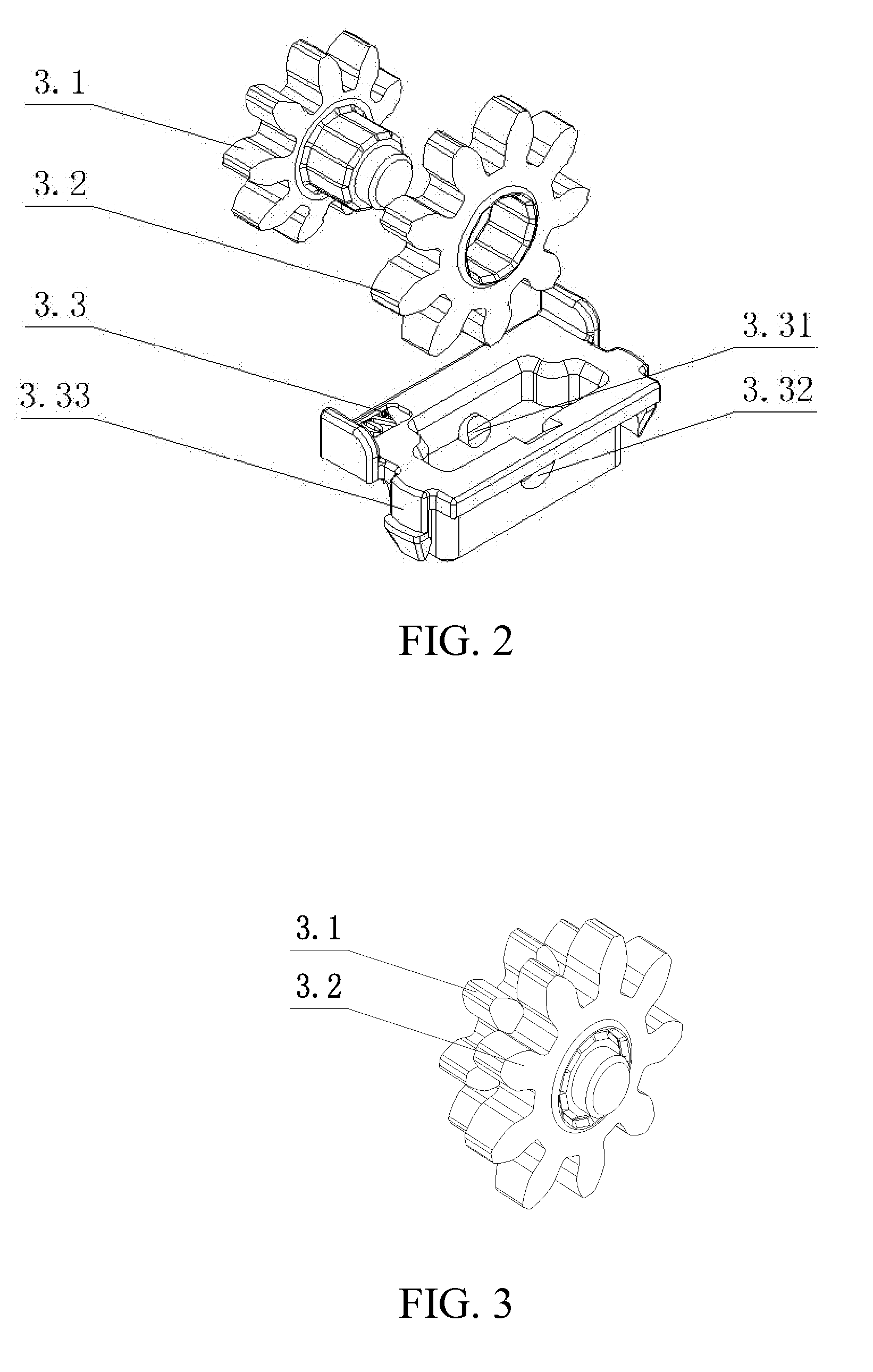
[0021]As shown in FIG. 1, This gear mechanism 3 used for slide rail comprises a movable rail A, a middle rail B and a fixed rail C which are mutually nested, an upper gear rack 1 is provided between the movable rail A and the middle rail B; a lower gear rack 2 is provided between the middle rail B and the fixed rail C; characterized in that, a gear mechanism 3 is engaged between the upper rack 1 and the lower rack 2; at least two gears respectively engaged with the upper gear rack 1 and the lower gear rack 2 are provided on the gear mechanism; two gears are closely coordinated and assembled through polygonal column and polygonal hole; when the acting force is greater than a certain value, two gears make relative slipping rotation; when the acting force is less than a certain value; two gears make synchronous rotation. This design can re...


PUM


Abstract

A gear mechanism used for slide rail, comprising a movable rail, a middle rail and a fixed rail which are mutually nested, an upper gear rack is provided between the movable rail and the middle rail; a lower gear rack is provided between the middle rail and the fixed rail; characterized in that, a gear mechanism is engaged between the upper rack and the lower rack; at least two gears respectively engaged with the upper gear rack and the lower gear rack are provided on the gear mechanism; two gears are closely coordinated and assembled through polygonal column and polygonal hole; when the acting force is greater than a certain value, two gears make relative slipping rotation; when the acting force is less than a certain value; two gears make synchronous rotation. The present invention is provided with a gear mechanism, the gear mechanism also comprises a A gear and a B gear, which are closely coordinated and assembled through polygonal column and polygonal hole respectively; when the acting force is greater than a certain value, the polygonal hole is expanded and two gears make relative slipping rotation; when the acting force is less than a certain value, two gears make synchronous rotation.

Description

FIELD OF THE INVENTION[0001]The present invention relates to a gear mechanism and in particular relates to a gear mechanism used for slide rail.BACKGROUND OF THE PRIOR ART[0002]The drawers available on the market generally use slide rails, and the slide rails with racks engaged with gears have gradually appeared. On Jul. 11, 2012, Chinese patent (documentation number: CN 102551380 A) disclosed a drawer slide rail, comprising an outer slide rail, an inner slide rail and an outer fixing rail, wherein the internal side rail is in slidable connection with the outer slide rail through a first holder, the inner slide rail is in slidable connection with the outer fixing rail through a second holder, characterized in that, duplicate gears are provided on the top or side of the inner slide rail, two gear sets of the duplicate gears are respectively in synchronous transmission connection with the first rack provided on the first holder and the second rack provided on the second holder. In the...

Claims


Application Information

Patent Timeline
Patent Type & Authority Applications(United States)
IPC IPC(8): A47B88/10F16H19/04A47B88/00A47B88/49A47B88/493
CPCA47B88/10A47B88/0085A47B2210/0048A47B2088/0088A47B2210/0075F16H19/04A47B2210/0013A47B2210/0059A47B2210/007A47B88/49
Inventor NG, TAI WAI
Owner GUANGDONG TAIMING METAL PROD
Learn More