Image forming apparatus, image forming method, and storage medium

a technology of image forming apparatus and forming method, which is applied in the field of image forming, can solve the problems of increasing the radiation noise produced by the image forming apparatus

Active Publication Date: 2016-05-05
CANON KK
View PDF1 Cites 5 Cited by
  • Summary
  • Abstract
  • Description
  • Claims
  • Application Information

AI Technical Summary

Benefits of technology

[0009]According to the present disclosure, both of assurance of density and suppressi

Problems solved by technology

Thus, the technique is problematic in that radiation n

Method used


Image

  • Image forming apparatus, image forming method, and storage medium
  • Image forming apparatus, image forming method, and storage medium
  • Image forming apparatus, image forming method, and storage medium

Examples


Embodiment Construction

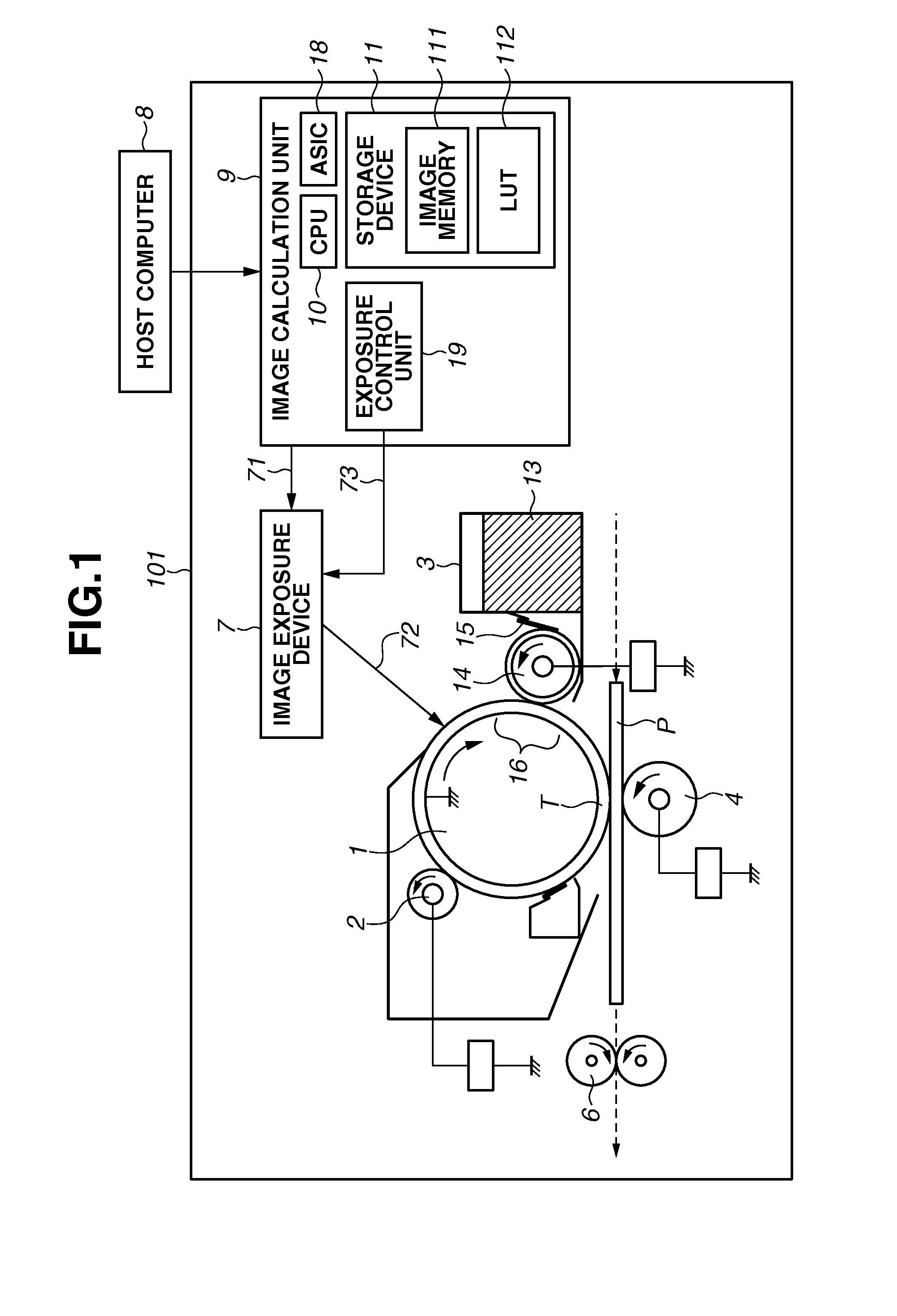
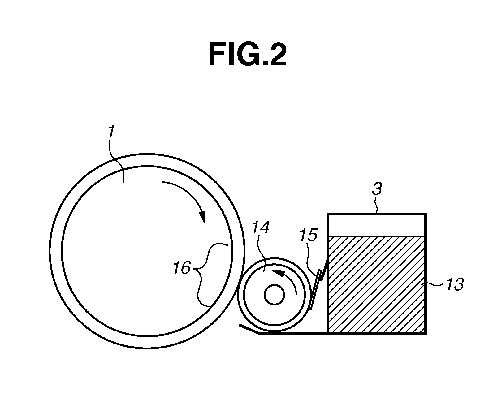
[0026]An operation of an image forming apparatus 101 according to a first exemplary embodiment is hereinafter described with reference to FIG. 1. The image forming apparatus 101 includes a drum-shaped electrophotographic photosensitive member (hereinafter referred to as “photosensitive drum”) 1 serving as an image bearing member. A charging device 2, which serves as a charging unit such as a charging roller, uniformly charges a surface of the photosensitive drum 1. An exposure device 7, which serves as an exposure unit such as a laser beam scanner device and a surface emitting element, exposes the uniformly charged photosensitive drum 1 by emitting thereto an amount of light based on image data. Accordingly, exposure is performed by using laser beams. An electrostatic latent image is formed on the surface of the photosensitive drum 1 as a result of the exposure. As used herein, the term “unit” generally refers to any combination of software, firmware, hardware, or other component, s...


PUM


Abstract

An image forming apparatus includes a setting unit configured to set a thinning amount smaller than one pixel for each line data in a high density area in image data, a comparison unit configured to compare the thinning amount set by the setting unit with a predetermined threshold, and a processing unit configured to execute, based on a result of comparison by the comparison unit, a thinning process by using a thinning amount larger than the thinning amount set by the setting unit or a thinning amount smaller than the thinning amount set by the setting unit as for M pixels out of N pixels (N>M) contained in the line data, and a thinning process by using the thinning amount set by the setting unit as for the rest of the N pixels contained in the line data.

Description

BACKGROUND OF THE INVENTION[0001]1. Field of the Invention[0002]The present disclosure generally relates to image forming and, more particularly, to an image forming apparatus, an image forming method, a storage medium, and to a technique for reducing a consumption amount of color material such as toner.[0003]2. Description of the Related Art[0004]There is a strong demand for reduction of a toner amount consumed by an image forming apparatus. A technique for reducing a toner consumption amount by lowering exposure intensity in an image area having a predetermined dimension has been proposed.[0005]There is a phenomenon known as a sweep-up, which produces such a state that a developing toner amount at a rear end of a latent image becomes larger than a developing toner amount at a flat portion of the latent image. Regarding this phenomenon, Japanese Patent Application Laid-Open No. 2007-272153 discusses a technique for replacing high density image data at a rear end of a latent image w...

Claims


Application Information

Patent Timeline
IPC IPC(8): G06F3/12G03G15/00G06K15/02
CPCG06F3/1219G03G15/556G06K15/029G06F3/1234G03G15/5025G06K15/128G06K15/1869
Inventor NAKAMURA, YASUYUKI
Owner CANON KK
Why Eureka
Try Eureka