Illumination estimation device, illumination estimation method, and storage medium

Active Publication Date: 2016-04-28
NEC CORP
View PDF6 Cites 4 Cited by
  • Summary
  • Abstract
  • Description
  • Claims
  • Application Information

AI Technical Summary

Benefits of technology

The present invention allows for the accurate estimation of the color of illumination in images that contain multiple colors. This is done without being affected by external light or the surface texture of the object being observed. This technology can even measure the color of illumination when there is a lot of ambient light present.

Problems solved by technology

However, it is difficult to accurately acquire object information from observed spectra.
It is impossible to accurately acquire object information even with use of the observed spectra as described above.
This method causes disadvantages such as a cost increase and system oversizing.
Specifically, it may be impossible to physically install an illumination light measuring sensor, or a large amount of labor or a large amount of cost may be required even if it is possible to install an illumination light measuring sensor.
Therefore, the assumption that it is possible to express the spectral reflectance of an intended object to be observed by using a model whose spectral reflectance is known is not always useful.
Thus, in the method based on the aforementioned assumption, it is not always possible to accurately estimate spectral characteristics of illumination with respect to an intended object to be observed.

Method used


Image

  • Illumination estimation device, illumination estimation method, and storage medium
  • Illumination estimation device, illumination estimation method, and storage medium
  • Illumination estimation device, illumination estimation method, and storage medium

Examples


first exemplary embodiment

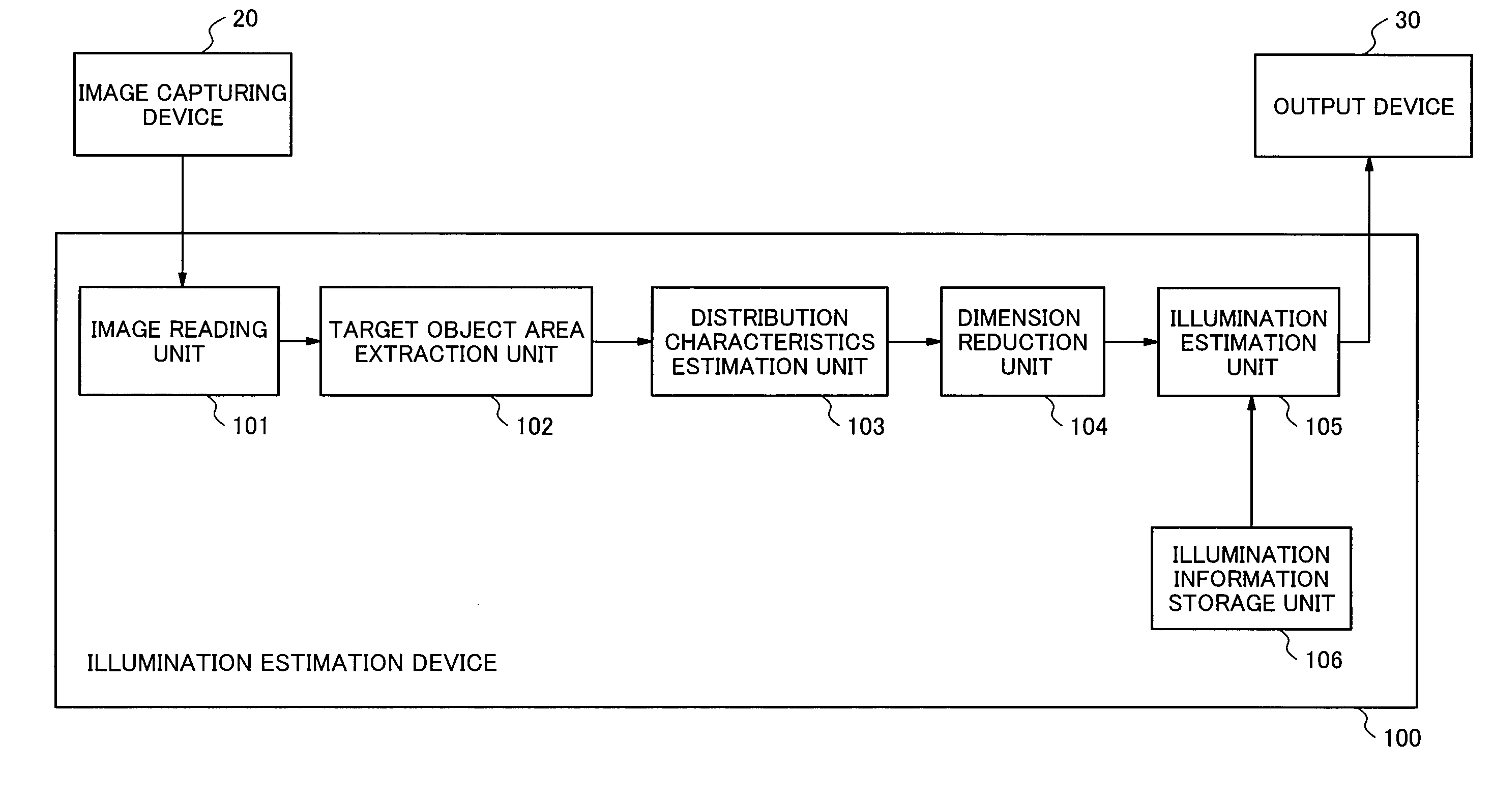
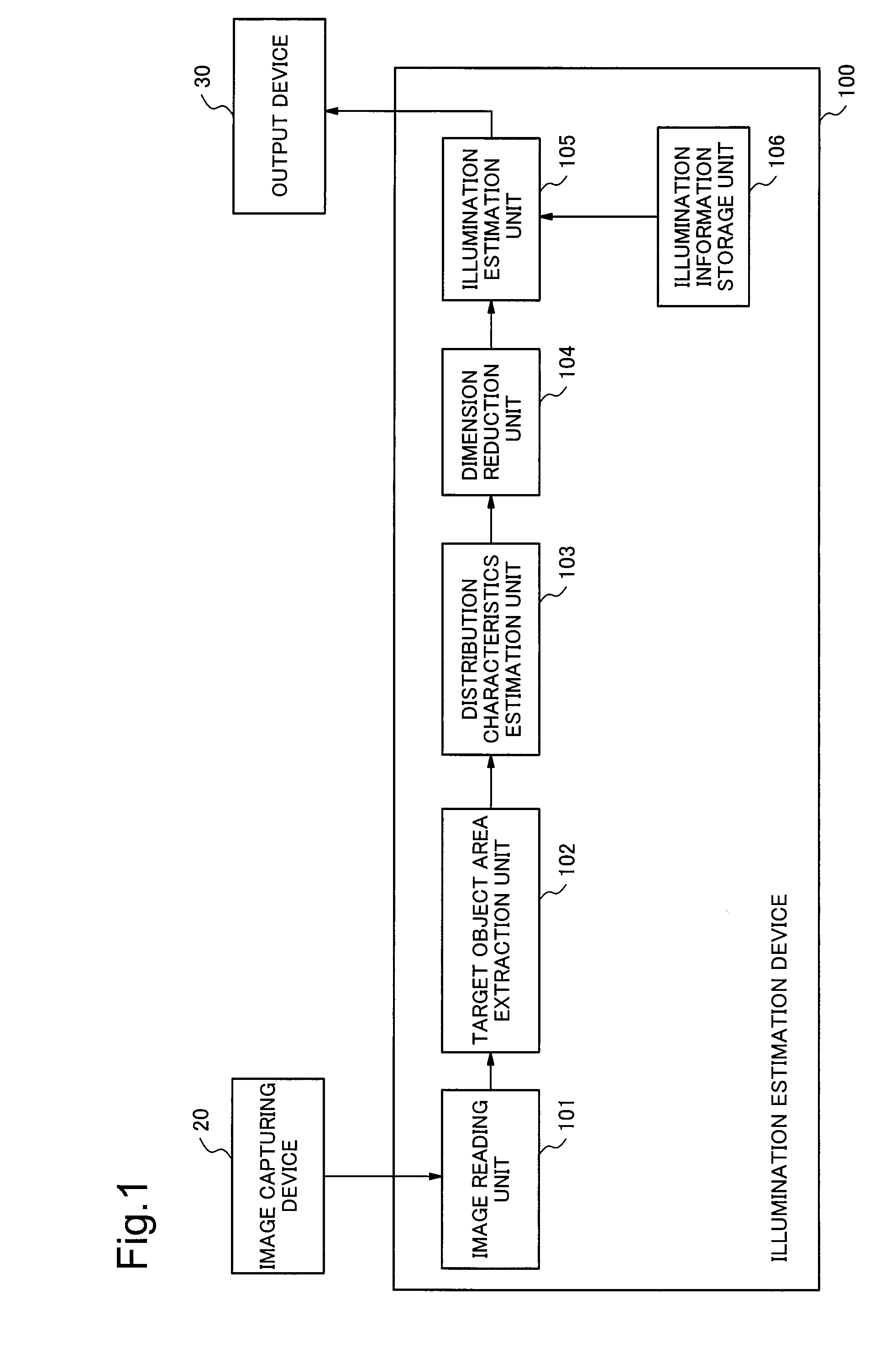
[0044]In the following, an exemplary embodiment of the invention is described referring to the drawings. FIG. 1 is a block diagram illustrating a configuration example of an illumination estimation device in the first exemplary embodiment of the invention. An illumination estimation device 100 illustrated in FIG. 1 includes an image reading unit 101, a target object area extraction unit 102, a distribution characteristics estimation unit 103, a dimension reduction unit 104, an illumination estimation unit 105, and an illumination information storage unit 106.

[0045]The image reading unit 101 reads an image captured by an image capturing device 20.

[0046]The target object area extraction unit 102 extracts an area including a specular reflection component of an object (hereinafter, referred to as an object area) from the image read by the image reading unit 101. It is possible to use an existing method as the object area extraction method.

[0047]The distribution characteristics estimatio...

second exemplary embodiment

[0083]Next, the second exemplary embodiment of the invention is described. FIG. 4 is a block diagram illustrating a configuration example of an illumination estimation device in the second exemplary embodiment of the invention. An illumination estimation device 200 illustrated in FIG. 4 includes the image reading unit 101, the target object area extraction unit 102, a distribution characteristics estimation unit 203, a dimension reduction unit 204, and an illumination estimation unit 205. The image reading unit 101 and the target object area extraction unit 102 in the second exemplary embodiment may be the same as those in the first exemplary embodiment. Therefore, the image reading unit 101 and the target object area extraction unit 102 in the second exemplary embodiment are indicated with the same reference signs as those in the first exemplary embodiment, and description thereof is omitted herein. In addition, the illumination information storage unit 106 is not necessary in the ...


PUM


Abstract

Illumination estimation device includes: target object area extraction unit which extracts an object area from a multispectral image, the object area being an area, including specular reflection, of an object; distribution characteristics estimation unit which estimates information representing a subspace that approximates a distribution of observation values in a spectral space, as distribution characteristics, the distribution characteristics being characteristics of a spreading manner of the observation values in the object area within the spectral space; dimension reduction unit which selects a distribution characteristic to be used from among the distribution characteristics estimated by the distribution characteristics estimation unit depending on the number of dimensions to be reduced, the number of dimensions to be reduced being determined in advance by a light environment; and illumination estimation unit which estimates spectral characteristics of illumination based on the subspace information to be represented by the distribution characteristic selected by the dimension reduction unit.

Description

TECHNICAL FIELD[0001]The present invention relates to an image processing technique, and more particularly, to an illumination estimation device, an illumination estimation method, and an illumination estimation program for estimating spectral characteristics of illumination from an image.BACKGROUND ART[0002]There is a method employing a multispectral image recorded with multi-wavelength light as a technique for grasping various pieces of information such as the kind, the material, and the state of an object in a captured scene with high precision. The behavior of light of each wavelength when the light is reflected on the surface of an object differs depending on the kind or the state of the object. Therefore, it is possible to grasp the kind or the state of an object by obtaining reflection characteristics of the object from observed spectra, which are observation values to be recorded at the respective pixels of the multispectral image.[0003]However, it is difficult to accurately...

Claims


Application Information

Patent Timeline
IPC IPC(8): H04N5/33H04N5/225
CPCH04N5/2256H04N5/332G01N21/27G06T2207/10024G06T7/90H04N23/11H04N23/56
Inventor KANEKO, EIJI
Owner NEC CORP
Why Eureka
Try Eureka