
Solar Panel Rack Assembly

a solar panel and rack technology, applied in the direction of solar heat collector mounting/support, solar heat collector safety, light and heating apparatus, etc., can solve the problems of high maintenance risk, high cost of solar array systems, and ineffective current solar energy production patterns in dealing with established consumption patterns. , to achieve the effect of minimizing the potential likelihood of damage to the solar panel, quick and easy replacement of components, and minimizing the profile of the solar panel

Inactive Publication Date: 2016-04-28
KRAUSE WILLIAM
View PDF10 Cites 29 Cited by
  • Summary
  • Abstract
  • Description
  • Claims
  • Application Information

AI Technical Summary

Benefits of technology

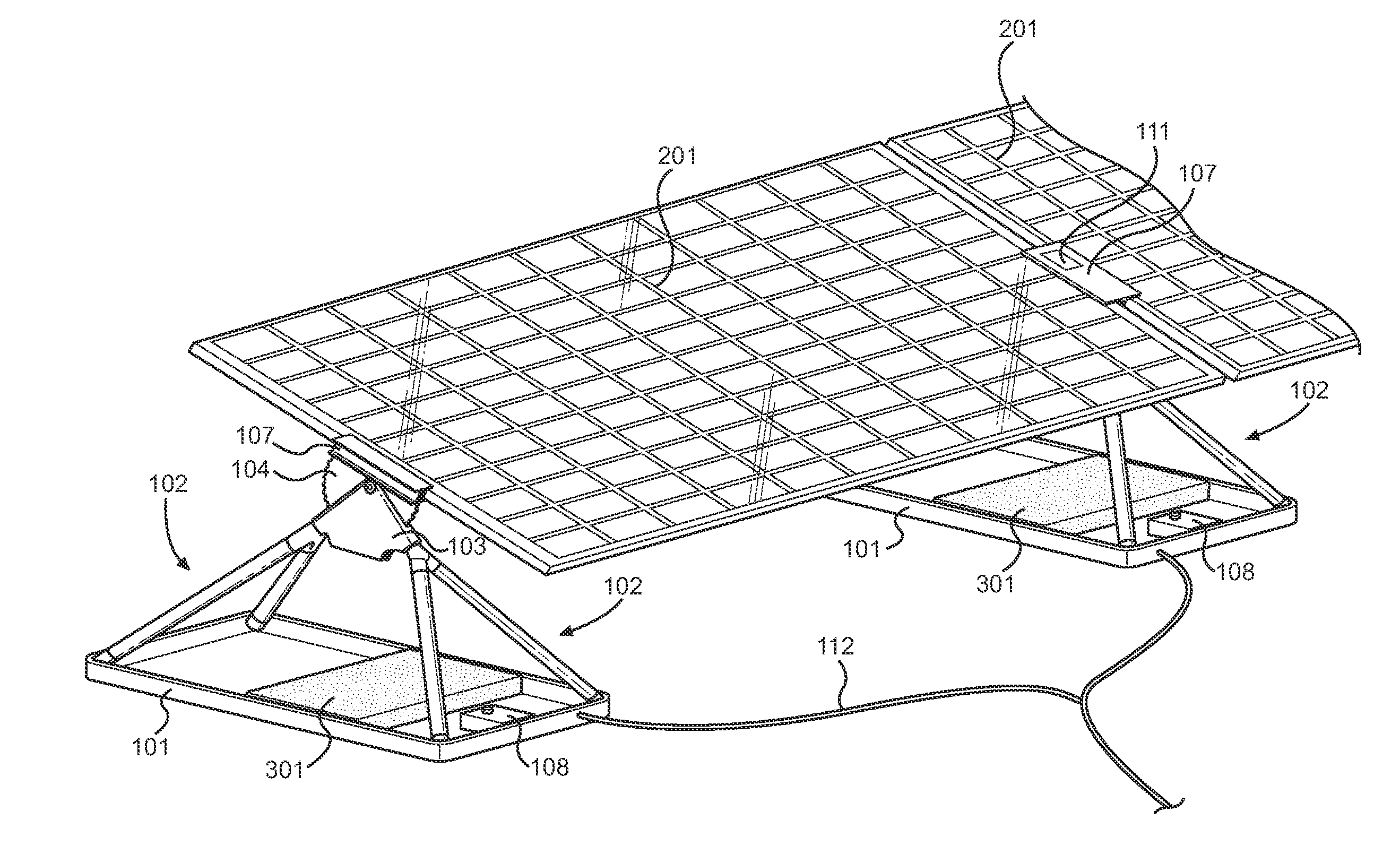
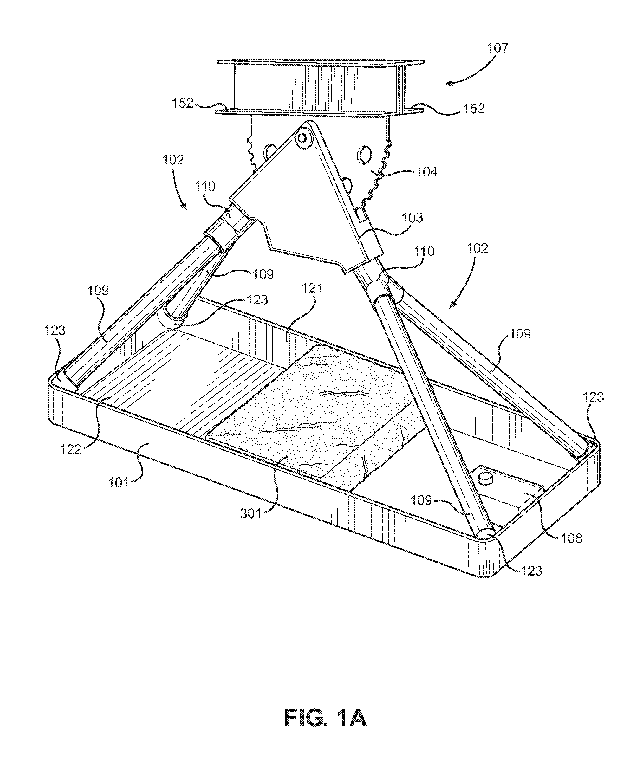
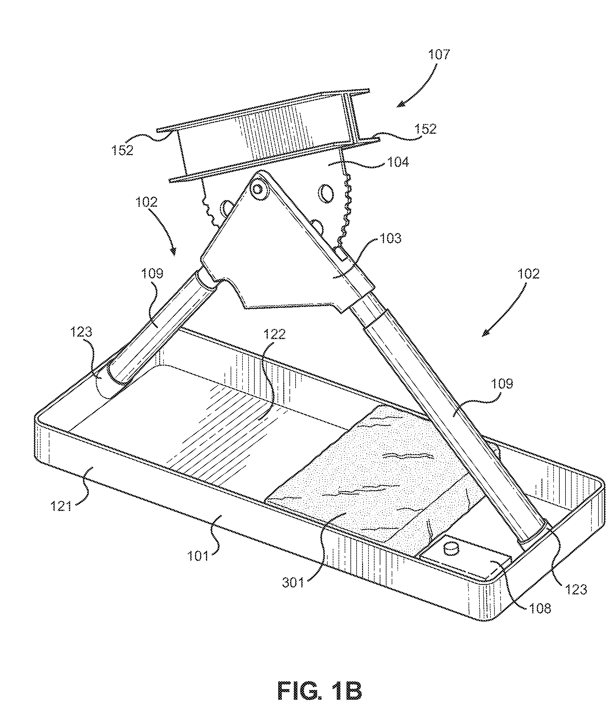
The present invention provides a solar panel racking assembly that uses micro motors, programmed controllers, and simple physics to minimize torque force. The rack assembly is a free-standing unit that does not require substantial superstructure or high-powered motorization, and is usable by a wide range of individuals without significant installation skill, time, or effort. The components of the rack assembly are interchangeable and removably connected, which allows for quick and easy replacement of damaged components. The rack assembly is designed to detect and adjust for high wind speeds to minimize the potential likelihood for damage to the solar panel and the rack assembly.

Problems solved by technology

The problem is that an overwhelming number of solar panel installations worldwide face south in the Northern hemisphere and north in the Southern hemisphere in a fixed position so that their kilowatt production occurs primarily over the midday period.
Therefore, grid failures primarily occur in late summer afternoons or early evenings and the current pattern of solar energy production is largely ineffective in dealing with these established consumption patterns.
Currently existing tracking systems for solar arrays are costly, cumbersome, and highly maintenance prone, so much so that most installations opt for the much less costly path of adding more inexpensive panels to fulfill array requirements, which in turn further compounds the problem of abundant supply when there are lower needs.

Method used


Image

  • Solar Panel Rack Assembly
  • Solar Panel Rack Assembly
  • Solar Panel Rack Assembly

Examples


Embodiment Construction

[0017]Reference is made herein to the attached drawings. Like reference numerals are used throughout the drawings to depict like or similar elements of the solar panel support assembly. The figures are intended for representative purposes only and should not be considered to be limiting in any respect.

[0018]An illustrative embodiment of the present solar panel support assembly is configured to support one or more solar panels and automatically adjust the angle at which the one or more solar panels are positioned throughout the day in order to track the movement of the sun. Tracking the movement of the sun maximizes the impingement of solar energy upon the one or more solar panels and thereby maximizes the power generated by the solar panel array. Furthermore, multiple solar panels are connectable in series via a panel lock device so that the solar panels in the array are movable in unison. An illustrative embodiment of the present solar panel support assembly is further configured t...


PUM


Abstract

A solar panel rack assembly. The assembly is configured to pivotably support one or more solar panels. A microcontroller and gear system adjusts the angle at which the solar panels supported by the assembly are disposed throughout the day, thereby allowing the solar panels to track the path of the sun, which maximizes the impingement of solar energy on the panels and more evenly distributes daily electrical production during daylight hours. The assembly includes a panel lock configured to simultaneously support multiple solar panels, which allows for the solar panels to be connected together in arrays without the need for a racking for each individual solar panel.

Description

CROSS REFERENCE TO RELATED APPLICATIONS[0001]This application claims the benefit of U.S. Provisional Application No. 62 / 068,956 filed on Oct. 27, 2014. The above identified patent application is herein incorporated by reference in its entirety to provide continuity of disclosure.BACKGROUND OF THE INVENTION[0002]The present invention relates to solar panel racking. Specifically, the present invention relates to solar panel racking configured to adjust the angle at which the solar panel array is disposed.[0003]The incorporation of solar energy production into the world's electrical energy system is well established. As a viable, near term contributor to fighting the undeniable polluting effects of fossil fuels and their effect on global warming and corresponding climate change, solar panels are rapidly becoming the physical embodiment of man's technological prowess to curb this life threatening atmospheric corruption. The problem is that an overwhelming number of solar panel installat...

Claims


Application Information

Patent Timeline
IPC IPC(8): H02S20/32H02S99/00
CPCH02S99/00H02S20/32F24S25/13F24S30/425F24S40/85F24S2025/02F24S2030/134Y02E10/47Y02E10/50
Inventor KRAUSE, WILLIAM
Owner KRAUSE WILLIAM
Learn More