
Cryogenic systems

a cryogenic system and cryogenic technology, applied in the field of cryogenic systems, can solve the problems of increasing the opportunity for deleterious changes in frozen specimens, reducing the integrity of samples, and needing extensive manipulation of samples

Active Publication Date: 2016-04-28
BIOLIFE SOLUTIONS INC
View PDF17 Cites 14 Cited by
  • Summary
  • Abstract
  • Description
  • Claims
  • Application Information

AI Technical Summary

Benefits of technology

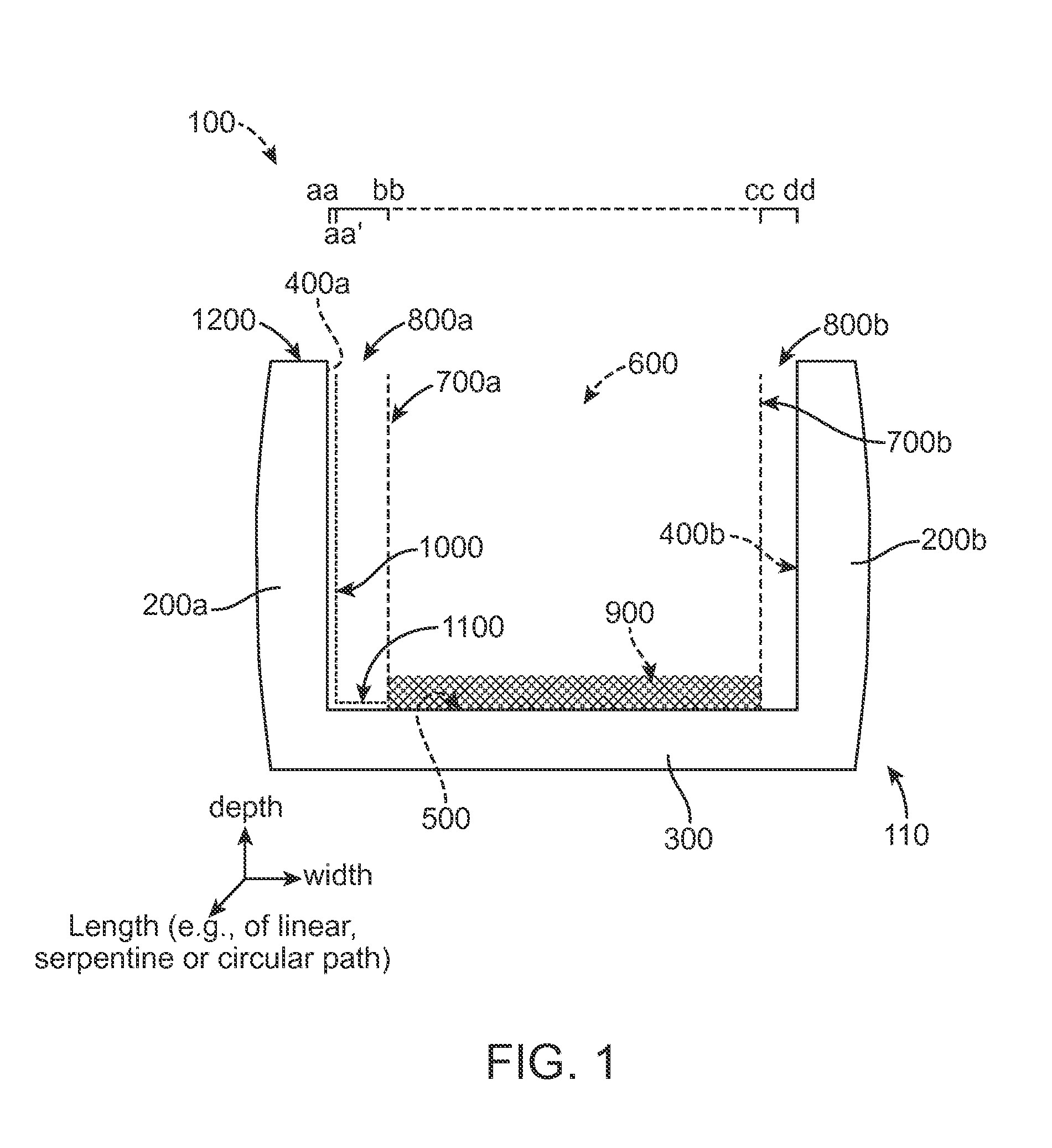
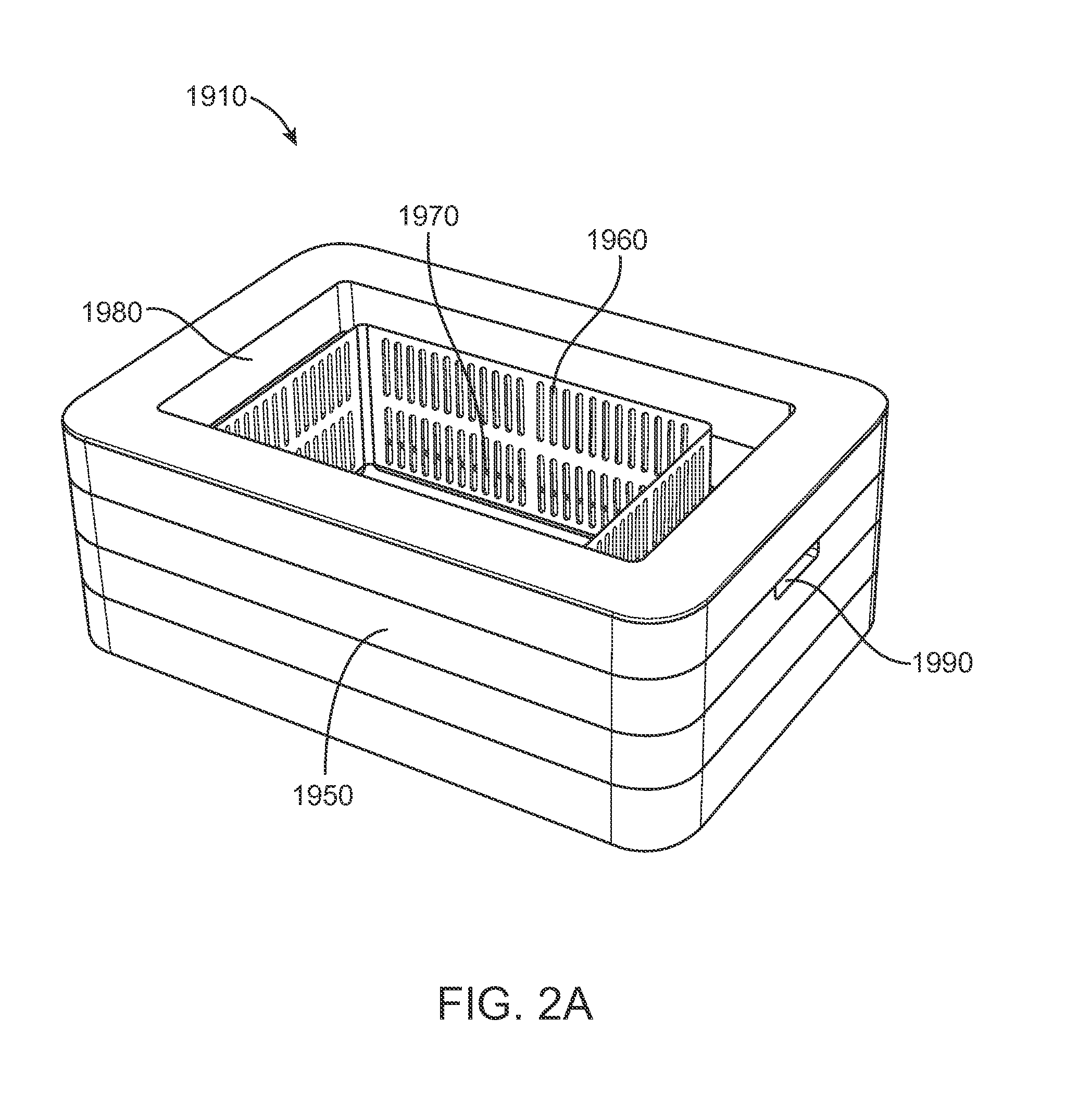
The patent describes a system for cryogenic processing, which involves using dry ice to cool down samples. The system includes an insulated chamber with a gas permeable dry ice retainer, which creates separate spaces for holding the dry ice and the samples. The dry ice retainer is positioned in the chamber to create a space above the chamber floor where the samples can be placed. The system also includes a container with a chamber and a gas permeable dry ice retainer positioned close to the chamber's interior walls. The dry ice retainer can hold dry ice pieces and exhaust CO2 gas directly into the chamber. The system can be used in a cryogenic processing laboratory or at room temperature. The technical effects of the system include efficient cooling of samples, reduced risk of damage to samples, and improved control of sample temperature.

Problems solved by technology

While frozen storage can be effective in decreasing the rate of sample degradation, in aqueous solutions and biological specimens, molecular activity does not cease until a temperature near −130° C. At temperatures above this point, there remains an opportunity for the specimen to re-order the solid structure, thereby creating changes in the specimen that may lead to a decrease in the integrity of the sample.
The opportunity for deleterious changes in frozen specimens increases greatly under conditions where the sample experiences transient fluctuations in temperature such as may occur when stored materials are transferred from one cold storage system to another, or when held inside a storage system that undergoes temperature spikes, such as those introduced when a freezer door is opened for normal access, during intervals of power failure, or even during normal mechanical refrigeration temperature cycles over time.
Despite the need for prevention of temperature spikes and fluctuations in samples, there is often a need for extensive manipulation of samples outside of the normal frozen storage system.

Method used


Image

  • Cryogenic systems
  • Cryogenic systems
  • Cryogenic systems

Examples


Embodiment Construction

I. Introduction

[0042]Materials stored in a frozen state at low temperature (e.g.; −70° C. to −50° C.) often require additional operations such as sorting, inventory, transfer, filling, boxing, labeling, cataloging, shipping, and location confirmation. Such operations typically require time intervals, spatial volumes, and access orientations that prohibit the performance of these operations inside conventional ultra-low temperature storage devices.

[0043]In one aspect, the present invention provides cryogenic workstations, or devices, for maintaining samples at an ultra-low temperature. In one aspect the device is used to maintain a low temperature zone that allows a human operator or robotic mechanism located in a zone of higher temperature to conduct extensive operations and manipulations on materials while maintaining them at low temperatures for optimal preservation of sample integrity. In one aspect, a low temperature zone is maintained during loading of a sample into the device....


PUM


Abstract

Cryogenic devices are provided in which solid carbon dioxide (dry ice) is used to maintain a temperature zone in which samples can be manipulated under conditions in which the sample is maintained at a temperature below −50 C.

Description

RELATED APPLICATIONS[0001]This application claims benefit of each of the following provisional applications No. 61 / 830,354 (filed Jun. 3, 2013); No. 61 / 860,801 (filed Jul. 31, 2013); No. 61 / 873,298 (filed Sep. 3, 2013); No. 61 / 879,624 (filed Sep. 18, 2013); No. 61 / 890,036 (filed Oct. 11, 2013); and No. 61 / 928,367 (filed Jan. 16, 2014). The entire content of each of these applications is incorporated herein by reference for all purposes.FIELD OF THE INVENTION[0002]The invention relates to systems for maintaining samples at ultra-low temperatures.BACKGROUND OF THE INVENTION[0003]Many industrial, commercial, and research processes require, for optimal results, that an object or material be maintained at a low temperature. For example, cryogenic preservation or maintenance at low temperature is a common means of insuring the molecular integrity of specimens and products. Substances that would degrade in a relatively short interval at higher temperatures can be stored with limited or no ...

Claims


Application Information

Patent Timeline
Patent Type & Authority Applications(United States)
IPC IPC(8): B01L7/00F25D3/12
CPCF25D3/125B01L7/50C12M45/22B01L7/04B01L2200/025B01L2200/143B01L2300/025B01L2300/0854B01L2300/1894
Inventor SCHRYVER, BRIAN
Owner BIOLIFE SOLUTIONS INC
Learn More