
Sensor device, liquid crystal display device, sensing method and program

a liquid crystal display and sensor technology, applied in the direction of static indicating devices, optical radiation measurement, instruments, etc., can solve the problem of difficulty in matching the brightness of the backlight with and achieve the effect of reducing the time until the brightness is adjusted to the brightness desired by users

Active Publication Date: 2016-04-21
SHARP NEC DISPLAY SOLUTIONS LTD
View PDF2 Cites 7 Cited by
  • Summary
  • Abstract
  • Description
  • Claims
  • Application Information

AI Technical Summary

Benefits of technology

The sensor device helps to quickly adjust the brightness to the level desired by the user.

Problems solved by technology

Consequently, it is difficult to match the brightness of the backlight with the brightness desired by the user, by only a simple control based on the brightness designated by the user, independently of the individual differences and the operating conditions, without losing the color balance while mixing three colors of R, G, and B (more colors depending on the backlight).

Method used


Image

  • Sensor device, liquid crystal display device, sensing method and program
  • Sensor device, liquid crystal display device, sensing method and program
  • Sensor device, liquid crystal display device, sensing method and program

Examples


Embodiment Construction

[0036]Hereunder, a sensor device according to a first exemplary embodiment of the present invention will be described with reference to the drawings.

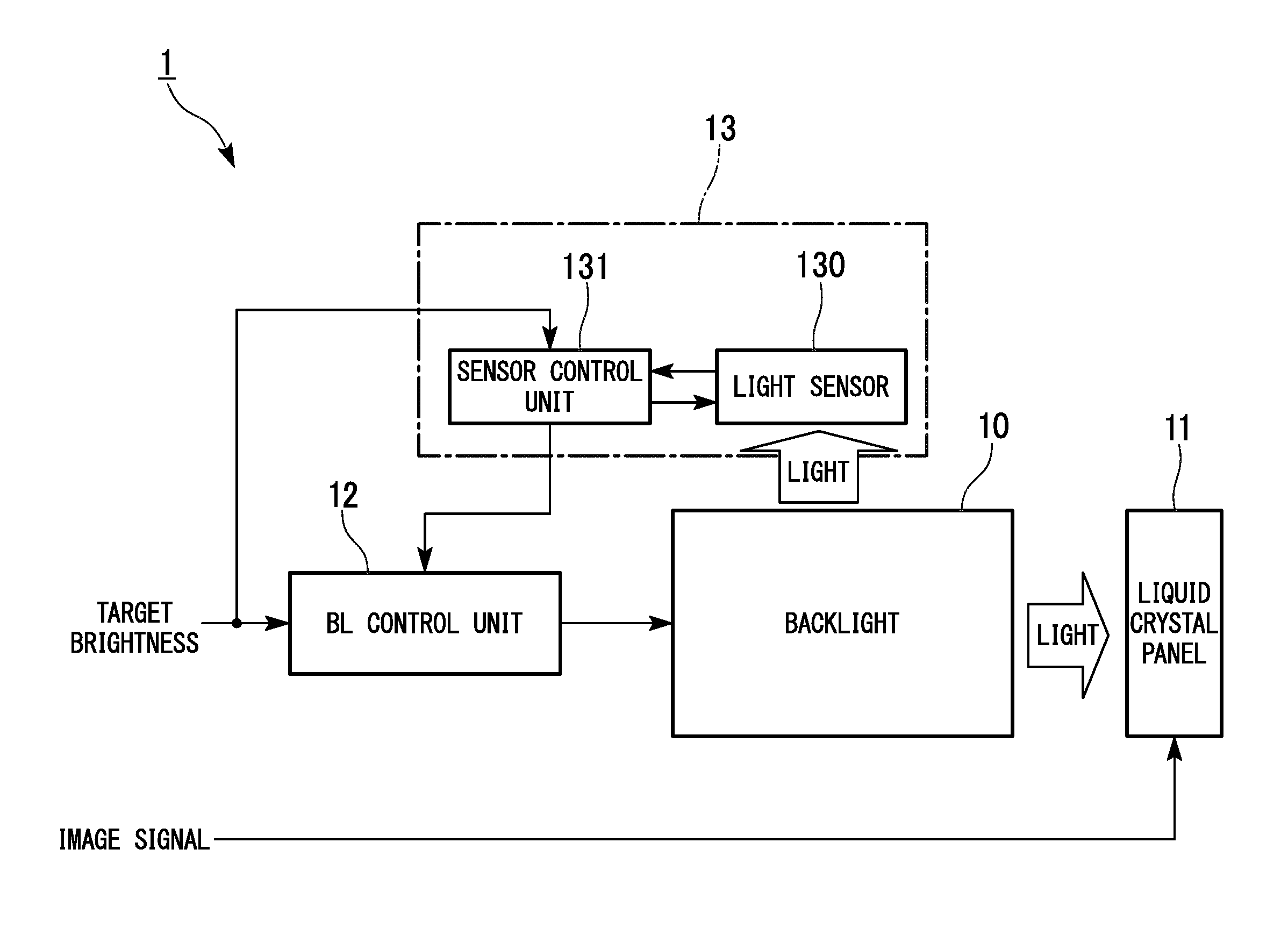
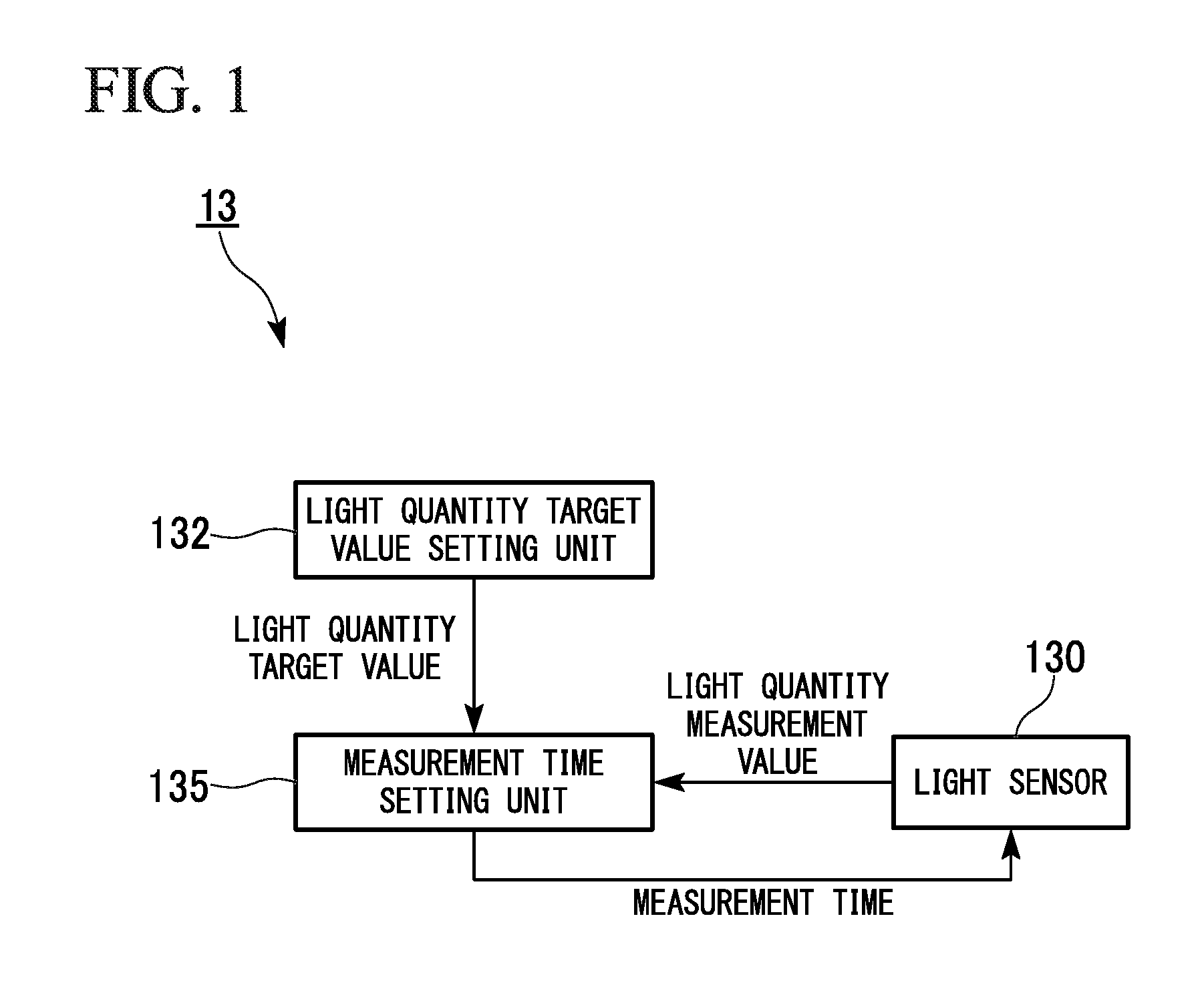
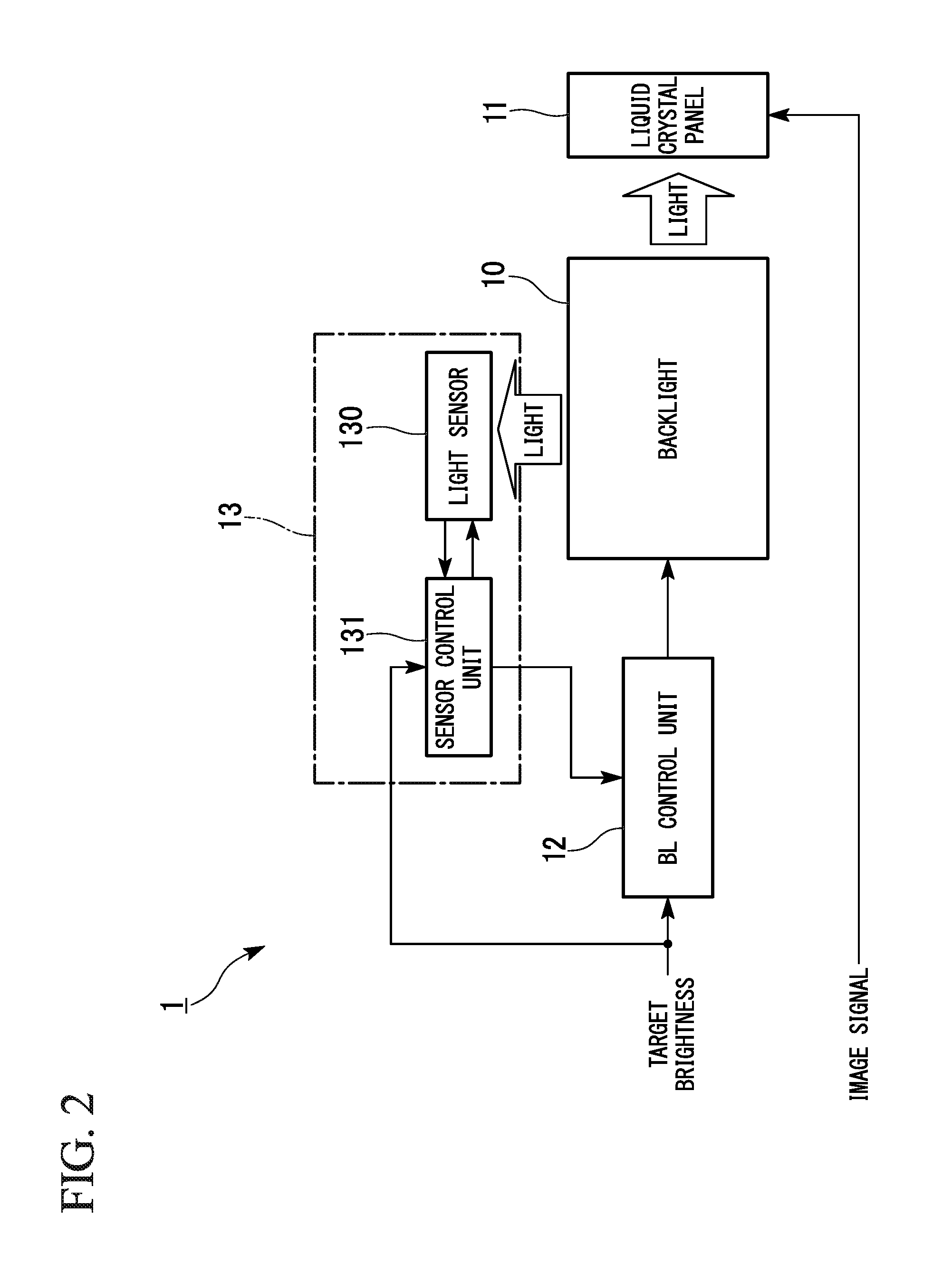
[0037]FIG. 1 is a diagram showing a minimum configuration of a sensor device according to the first exemplary embodiment of the present invention. In this figure, reference symbol 13 denotes the sensor device.

[0038]As shown in FIG. 1, the sensor device 13 includes a light sensor 130 that acquires a light quantity measurement value that is proportional to a product of a light quantity of a backlight and a measurement time, and a light quantity target value calculating unit 132 that calculates a light quantity target value based on a user setting for the backlight. Moreover, the sensor device 13 includes a measurement time calculating unit 135 that calculates a measurement time for when the light sensor 130 acquires the light quantity measurement value a next time, based on the light quantity measurement value acquired by the light sensor...


PUM


Abstract

A sensor device includes: a light sensor that acquires a first light quantity measurement value that is proportional to a light quantity of a backlight and a first measurement time; a light quantity target value calculating unit that calculates a light quantity target value based on a user setting for the backlight; and a measurement time calculating unit that calculates a second measurement time for when the light sensor acquires a second light quantity measurement value a next time, based on the acquired first light quantity measurement value and the light quantity target value.

Description

TECHNICAL FIELD[0001]The present invention relates to a sensor device that senses a light quantity of a backlight, a sensing method, a liquid crystal display device that uses the sensor device or the sensing method, and a program.BACKGROUND ART[0002]An LED backlight using an LED (Light Emitting Diode) as a light source has been adopted for recent liquid crystal display devices. Moreover, some of the recent LED backlights can control the light quantity for each of R (red), G (green), and B (blue) (or for each part thereof) individually, and can adjust a color balance of the backlight in addition to a brightness of the backlight.[0003]The liquid crystal display device using the above-described LED backlight can generally change the brightness of the backlight to a brightness desired by a user, for example, based on a designation by the user. However, because the LED has an individual difference in an actual color or light quantity, the brightness or a color balance may be different fo...

Claims


Application Information

Patent Timeline
IPC IPC(8): G09G3/34H05B33/08G01J1/42H05B37/02H05B44/00
CPCG09G3/3406H05B37/0227G09G2320/064G01J1/42G09G2360/145H05B33/0848G09G3/3413G09G2320/0666G01J1/4209G01J1/0228H05B45/12H05B47/11H05B45/22Y02B20/40H05B45/14
Inventor MATSUI, KATSUYUKI
Owner SHARP NEC DISPLAY SOLUTIONS LTD
Learn More