
System and method for parallel power and blackout protection for electric powered hydraulic fracturing

a technology of electric power and hydraulic fracturing, applied in emergency power supply arrangements, instruments, borehole/well accessories, etc., can solve the problems of limited redundancy and blackout protection, insufficient remaining power to continue pumping operations, and the entire system could cease to function, so as to prevent hydraulic fracturing system overload

Active Publication Date: 2016-04-14
US WELL SERVICS LLC
View PDF10 Cites 201 Cited by
  • Summary
  • Abstract
  • Description
  • Claims
  • Application Information

AI Technical Summary

Benefits of technology

This patent describes a system and method for preventing failure in a hydraulic fracturing system. The system includes a generator, load shedding system, and breaker to prevent overload of the system. The load shedding system monitors power draw of components, and a breaker is activated if a predetermined threshold is exceeded. The method also includes powering backup components in case of failure. Overall, this technology prevents failure of equipment, saves time, and increases efficiency in hydraulic fracturing operations.

Problems solved by technology

In such a system, all of the turbine generators are synced and tied together, which leads limited redundancy and blackout protection.
In practice, this means that if one of the turbines loses power, there will not be sufficient remaining power to continue pumping operations.
Thus, the entire system could cease to function, with negative consequences (e.g., a screen out) for the well.
In addition, even in systems where enough turbines remain serviceable to continue pumping the well to avoid a screen out, this function is not performed because the ability to shed load, such as by shutting down power to non-critical parts of the system, is limited.
The power draw from all of the units overloads the turbines causing a shutdown of the entire system.

Method used


Image

  • System and method for parallel power and blackout protection for electric powered hydraulic fracturing
  • System and method for parallel power and blackout protection for electric powered hydraulic fracturing
  • System and method for parallel power and blackout protection for electric powered hydraulic fracturing

Examples


Embodiment Construction

[0018]The foregoing aspects, features, and advantages of the present technology will be further appreciated when considered with reference to the following description of preferred embodiments and accompanying drawing, wherein like reference numerals represent like elements. In describing the preferred embodiments of the technology illustrated in the appended drawing, specific terminology will be used for the sake of clarity. However, the technology is not intended to be limited to the specific terms used, and it is to be understood that each specific term includes equivalents that operate in a similar manner to accomplish a similar purpose.

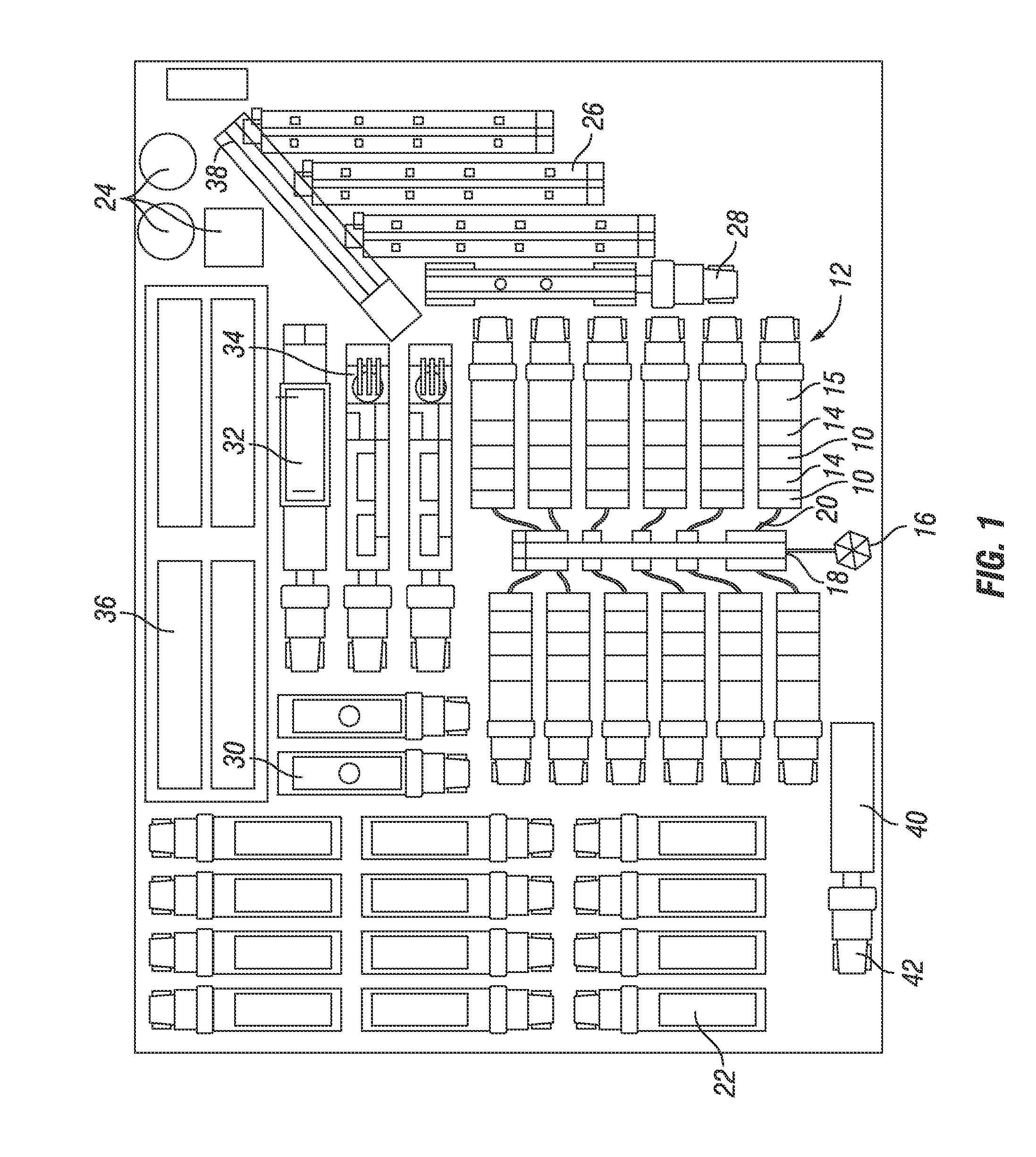
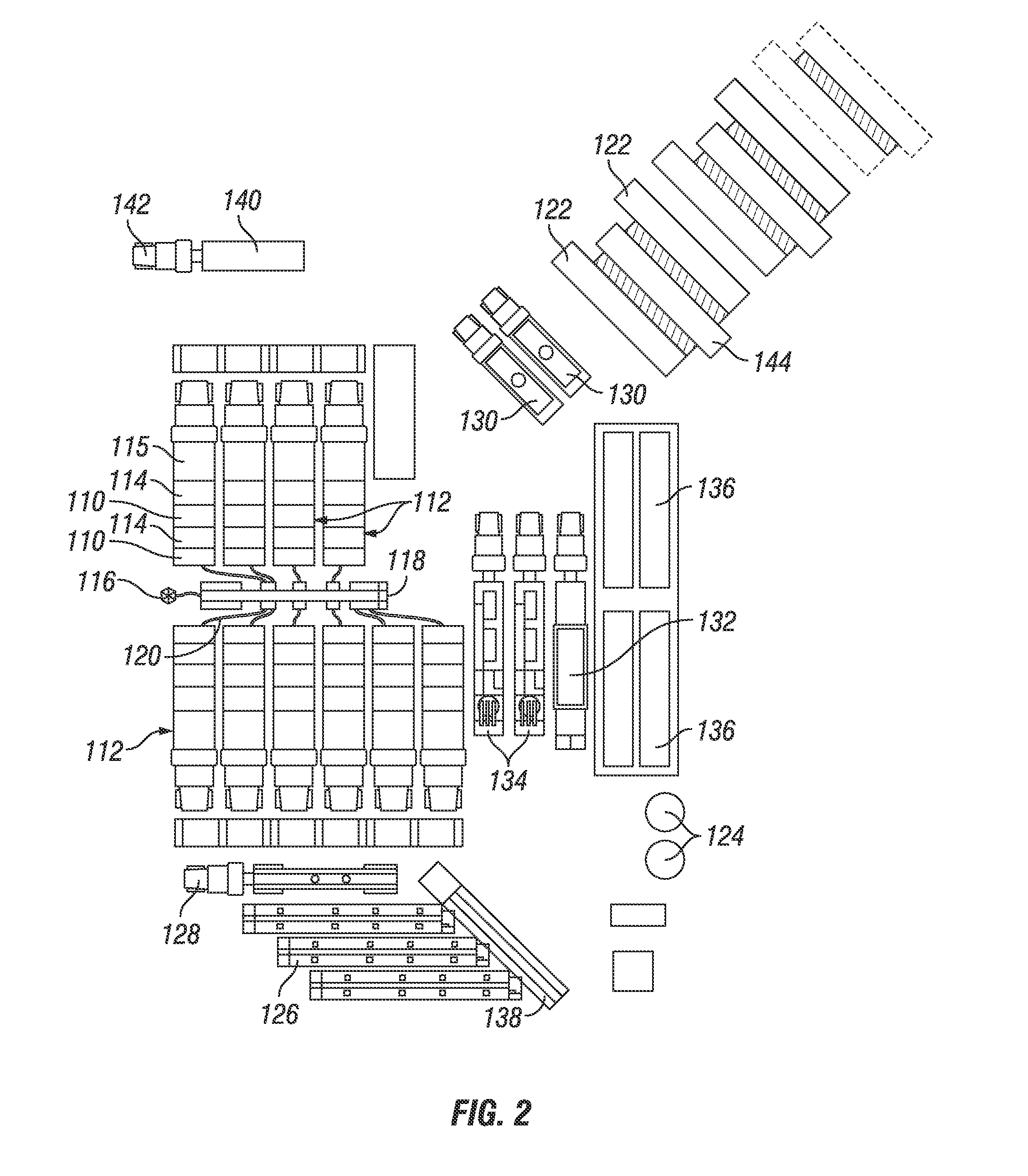
[0019]FIG. 1 shows a plan view of equipment used in a hydraulic fracturing operation. Specifically, there is shown a plurality of pumps 10 mounted to vehicles 12, such as trailers (as shown, for example, in FIGS. 3 and 4). In the embodiment shown, the pumps 10 are powered by electric motors 14, which can also be mounted to the vehicles 12. The pu...


PUM


Abstract

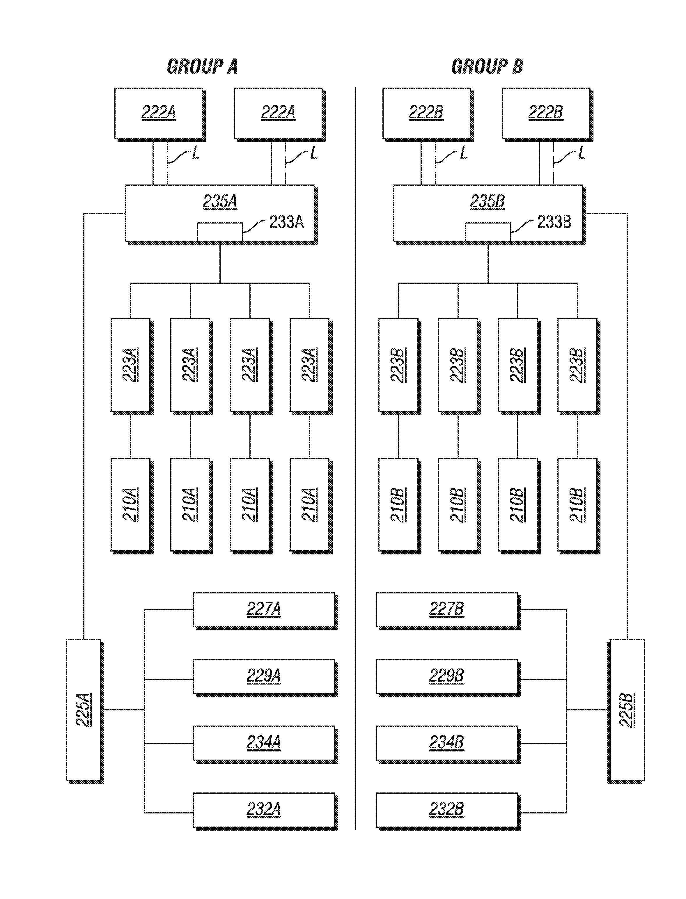
A system for powering equipment used in a hydraulic fracturing operation, the system including at least one first generator in electrical communication with a first switchgear for providing power to primary components of a hydraulic fracturing operation, and at least one second generator in electrical communication with a second switchgear for providing power to backup components of a hydraulic fracturing operation. The at least one first generator is independent of the at least one second generator so that if the at least one first generator loses the ability to generate electricity, the at least one second generator can continue to generate electricity.

Description

CROSS-REFERENCE to RELATED PATENT APPLICATIONS[0001]This application is a continuation-in-part of non-provisional U.S. patent application Ser. No. 13 / 679,689, filed Nov. 16, 2012, and claims priority to U.S. Provisional Patent Appln. No. 62 / 063,680, filed Oct. 14, 2015, the full disclosures of which are hereby incorporated herein by reference.BACKGROUND OF THE INVENTION[0002]1. Field of the Invention[0003]This technology relates to hydraulic fracturing in oil and gas wells. In particular, this technology relates to methods of powering electric hydraulic fracturing spreads.[0004]2. Brief Description of Related Art[0005]Typically, most equipment, including pumps used in hydraulic fracturing operations, are diesel powered, with each pump powered by a discrete diesel engine. If one pump goes out, the remaining pumps are unaffected, so that circulation in the well can be maintained by the still-functioning pumps.[0006]Some sites, however, utilize electric power to drive the pumps. In som...

Claims


Application Information

Patent Timeline
Patent Type & Authority Applications(United States)
IPC IPC(8): H02J3/00E21B43/26G05B15/02E21B41/00
CPCH02J3/005G05B15/02E21B43/26E21B41/0085H02J3/14H02J9/066Y04S20/248H02J2310/60E21B43/2607Y04S20/222Y02B70/3225
Inventor OEHRING, JAREDKURTZ, ROBERTZAUNBRECHER, BRENNAN
Owner US WELL SERVICS LLC
Learn More