Method of quantifying hydrocarbon formation and retention in a mother rock

a hydrocarbon and mother rock technology, applied in the field of methods of quantifying hydrocarbon formation and retention in mother rock, can solve the problems of kinetic parameters lag, uncertainty in the estimation of oil window, and difficulty in elaborating the reaction mechanism

Inactive Publication Date: 2016-04-07
INST FR DU PETROLE
View PDF0 Cites 4 Cited by
  • Summary
  • Abstract
  • Description
  • Claims
  • Application Information

AI Technical Summary

Problems solved by technology

's work of 1997 showed that the differences in the experimental conditions of the pyrolyses carried out (open or closed medium, in the presence or absence of water or of mineral matrix, or according to the grain size of the sample) leads to a kinetic parameters lag and therefore to an uncertainty in the estimation of the oil window.
On the other hand, the complexity of these models makes elaboration of the reaction mechanism difficult.
Finally, and above all, the very large number of reactions in these models is incompatible with current basin simulators.
The polymer solubility theory and this model thus do not totally explain the hydrocarbon composition differences between source rock extracts and reservoir oils, observed in petroleum systems.
Similarly, this model does not explain the great accumulation of aliphatic hydrocarbons in coals.
This model has two limitations: the first one is that the values of the swelling ratio are filed according to their chemical class but they are not normalized.
Thus, the model does not respect the mass conservation principle.
The second drawback is due to the fact that the swelling phenomenon involves swelling of the organic matrix.

Method used


Image

  • Method of quantifying hydrocarbon formation and retention in a mother rock
  • Method of quantifying hydrocarbon formation and retention in a mother rock
  • Method of quantifying hydrocarbon formation and retention in a mother rock

Examples


Embodiment Construction

[0063]The method according to the invention numerically models the thermal maturation of the organic matter of the source rock or of any other macromolecular system, and the retention of the products from this reaction in the residual organic matrix, and to possibly extrapolate the results to the basin scale.

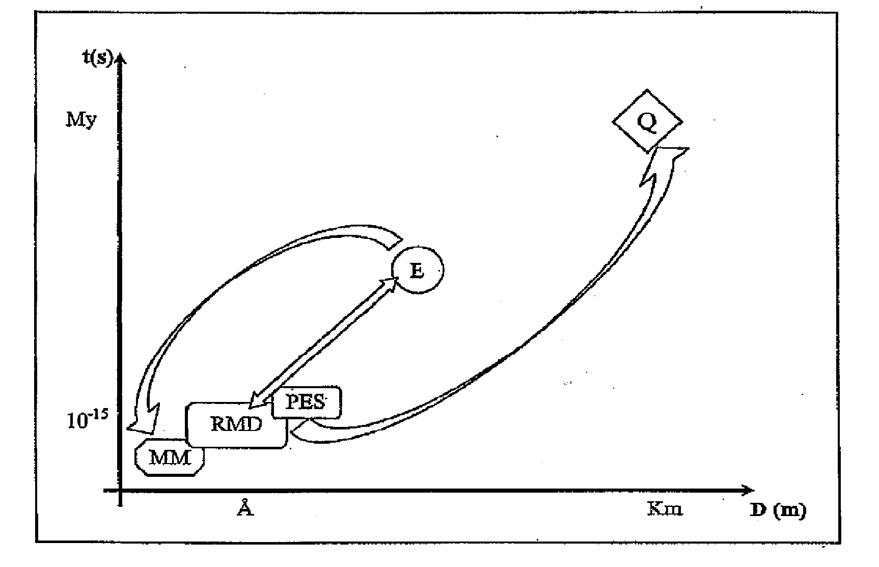
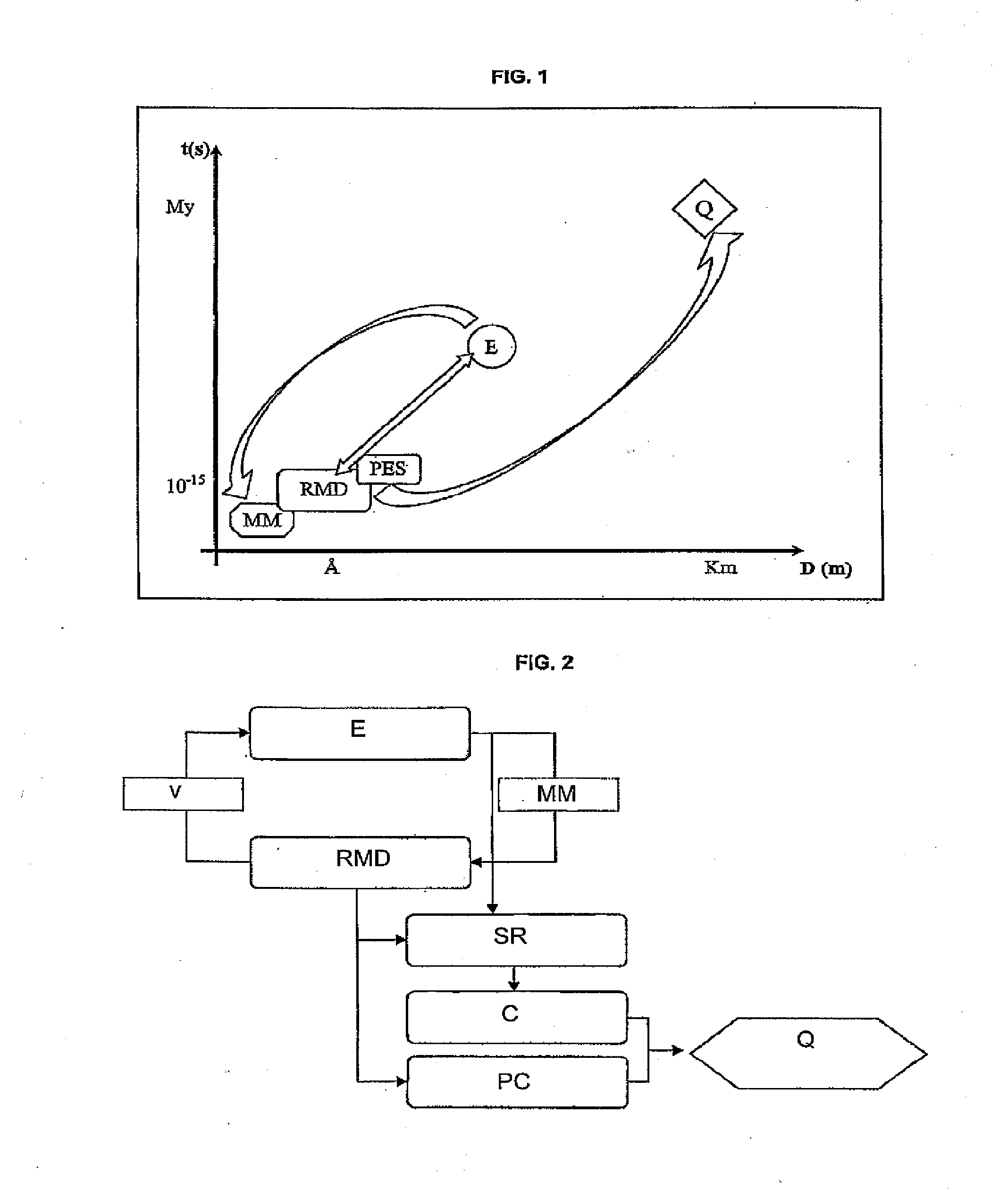
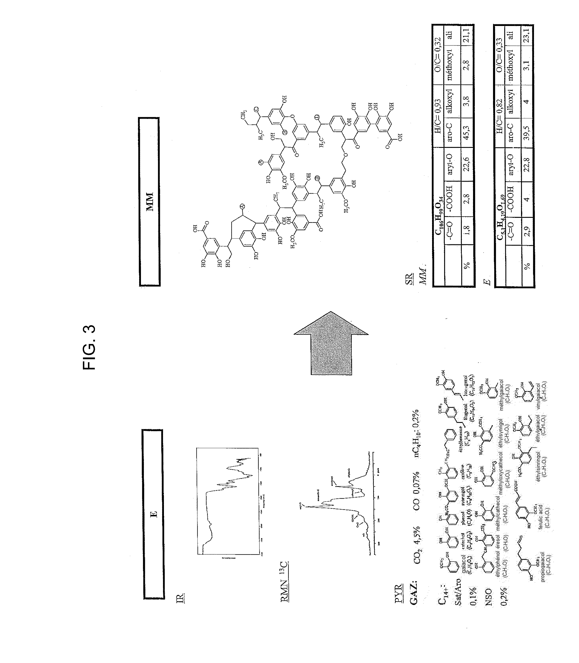
[0064]FIG. 1 shows the principle of the method as a function of the various space scales (D(m): Distance in meter) and time scales (t(s): time in second). The initial kerogen (or any other macromolecular structure) sample (E) is experimentally characterized, which allows determination of a molecular model of the structure (MM (Å, 10−15s)). This molecular model is the input datum of the dynamic simulations coupled with a reactive force field (RMD (Å, 10−15s)). These simulations model the thermal cracking reaction of the molecular model under the given conditions, and they are validated by comparison with the experimental thermal maturation data. At several stages of the simulated...


PUM


Abstract

The method according to the invention allows the formation of oil and the retention phenomenon in the source rock to be modelled. Organic matter characterization experiments are used to establish the molecular model (MM) of the initial sample (E). The thermal cracking reaction of this molecular model is reproduced by dynamic molecular simulation computations with a reactive force field (RMD) and validated by comparison with experimental data. The reaction mechanism obtained (SR) allows to carry out a kinetic study (C) by variation of the temperature parameter. The phase equilibria (PES) of the reaction medium are determined at any time from dynamic simulation. The successive phase equilibrium assessments at various progress stages of the cracking reaction allow following the physicochemical evolution (PC) of the thermal maturation of the organic sample studied. The free hydrocarbons (liquid and gaseous) that are not retained in the solid residue can be quantified throughout numerical modelling of the sample maturation; representing, in the sedimentary basins, the hydrocarbons that are not retained in the organic matrix of the source rock (Q). This quantity can be used as an indicator or an input value for the retention threshold in basin models.

Description

CROSS-REFERENCE TO RELATED APPLICATION[0001]This application is a divisional application of U.S. patent application Ser. No. 11 / 833,456, filed Aug. 3, 2007, the contents of which are incorporated herein by reference.BACKGROUND OF THE INVENTION[0002]1. Field of the Invention[0003]The present invention relates to a method of quantifying hydrocarbon formation and retention within a macromolecular chemical system.[0004]2. Description of the Prior Art[0005]The following documents, mentioned in the description hereafter, illustrate the state of the art:[0006]Behar F., Vandenbroucke M., Tang Y., Marquis F., Espitalié J., 1997. Thermal Cracking of Kerogen in Open and Closed Systems: Determination of Kinetic Parameters and Stoichiometric Coefficients for Oil and Gas Generation. Org. Geochem., 26, 5-6, 321-339.[0007]Burnham, A. K. and Braun, R. L., 1989. Development of Detailed Model of Petroleum Formation, Destruction, and Expulsion from Lacustrine and Marine Source Rocks. Advances in Organi...

Claims


Application Information

Patent Timeline
Patent Type & Authority Applications(United States)
IPC IPC(8): G06F19/00G01V99/00
CPCG01V99/005G06F19/701E21B49/00G01N33/241G01V99/00G01V2210/661G16C10/00
Inventor SALMON, ELODIELORANT, FRANCOISBEHAR, FRANCOISE
Owner INST FR DU PETROLE
Why Eureka
Try Eureka