Accelerator Force Feedback Pedal (AFFP) as Assistance System for Distance Control in Traffic

a technology of acceleration force and feedback pedal, which is applied in the direction of braking system, process and machine control, instruments, etc., can solve the problems of increasing complexity and expens

Inactive Publication Date: 2016-04-07
CONTI TEMIC MICROELECTRONIC GMBH
View PDF18 Cites 3 Cited by
  • Summary
  • Abstract
  • Description
  • Claims
  • Application Information

AI Technical Summary

Benefits of technology

[0023]In addition, it is advantageous, particularly given the increasing volume and density of traffic, to automatically control the distance from a vehicle that is driving ahead in the vehicle control system, without the need for visual or acoustic signals. In particular, in stressful traffic situations such as, for example, dense traffic at peak times, additional visual or acoustic signals could result in other information being overlooked or misinterpreted. It is therefore advantageous to assist the driver in the selection of an optimum distance from a vehicle that is driving ahead by means of clear, haptic information via the motor vehicle's accelerator device.
[0024]According to one embodiment of the invention, the control loop determines the nominal angle on the basis of a speed vact of the motor vehicle, a relative speed vrel of the motor vehicle to a motor vehicle that is driving ahead, a nominal distance dnom from the motor vehicle that is driving ahead and an actual distance dact from the motor vehicle that is driving ahead. The advantage of this is that all of the aforementioned variables can be determined with low technical outlay (e.g. effort and / or expense). The actual speed vact of the motor vehicle can thus be determined by a speedometer which is usually found in every motor vehicle. The distance of the motor vehicle from a motor vehicle that is driving ahead dact can be determined, for example, by a distance radar. The relative speed vrel of the motor vehicle to a motor vehicle that is driving ahead can be determined from the change in the distance dact over time. The nominal distance dnom is a freely definable variable. The nominal distance can, for example, be determined according to the regulations of the prevailing jurisdiction as a function of the speed vact of the motor vehicle or by a selected driving mode of the motor vehicle.

Problems solved by technology

Separate controllers make it possible to individually adjust the parameters of the controller and, thus, the latter's control behavior to the respective operating situation, but increase the complexity and expense, even if nowadays controllers are frequently constructed as a software control system, since memory space and computing time also have to be considered in software.

Method used


Image

  • Accelerator Force Feedback Pedal (AFFP) as Assistance System for Distance Control in Traffic
  • Accelerator Force Feedback Pedal (AFFP) as Assistance System for Distance Control in Traffic
  • Accelerator Force Feedback Pedal (AFFP) as Assistance System for Distance Control in Traffic

Examples


Embodiment Construction

[0036]Elements of the following embodiments, which correspond to one another or which are identical, are in each case identified below with the same reference numerals.

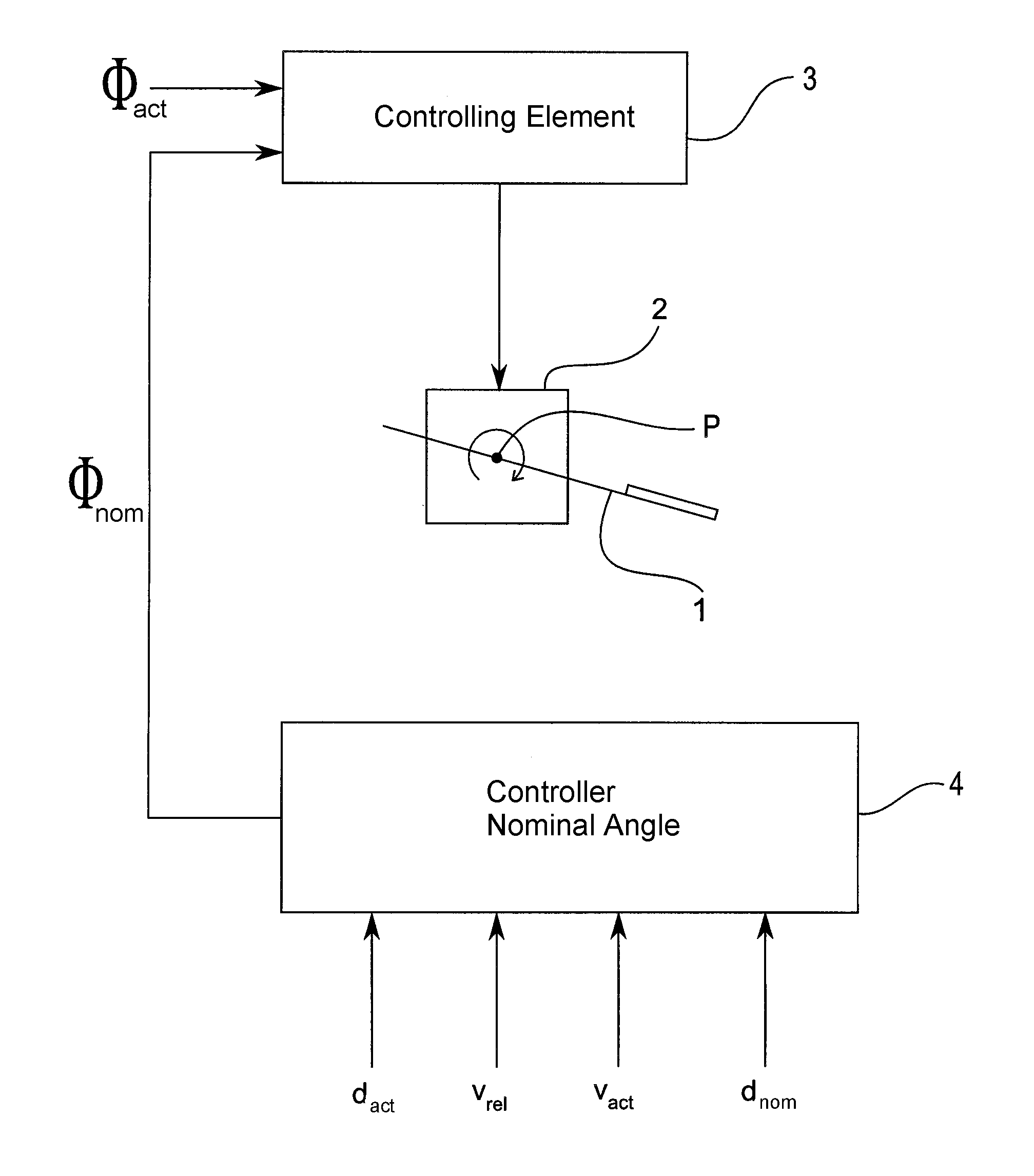
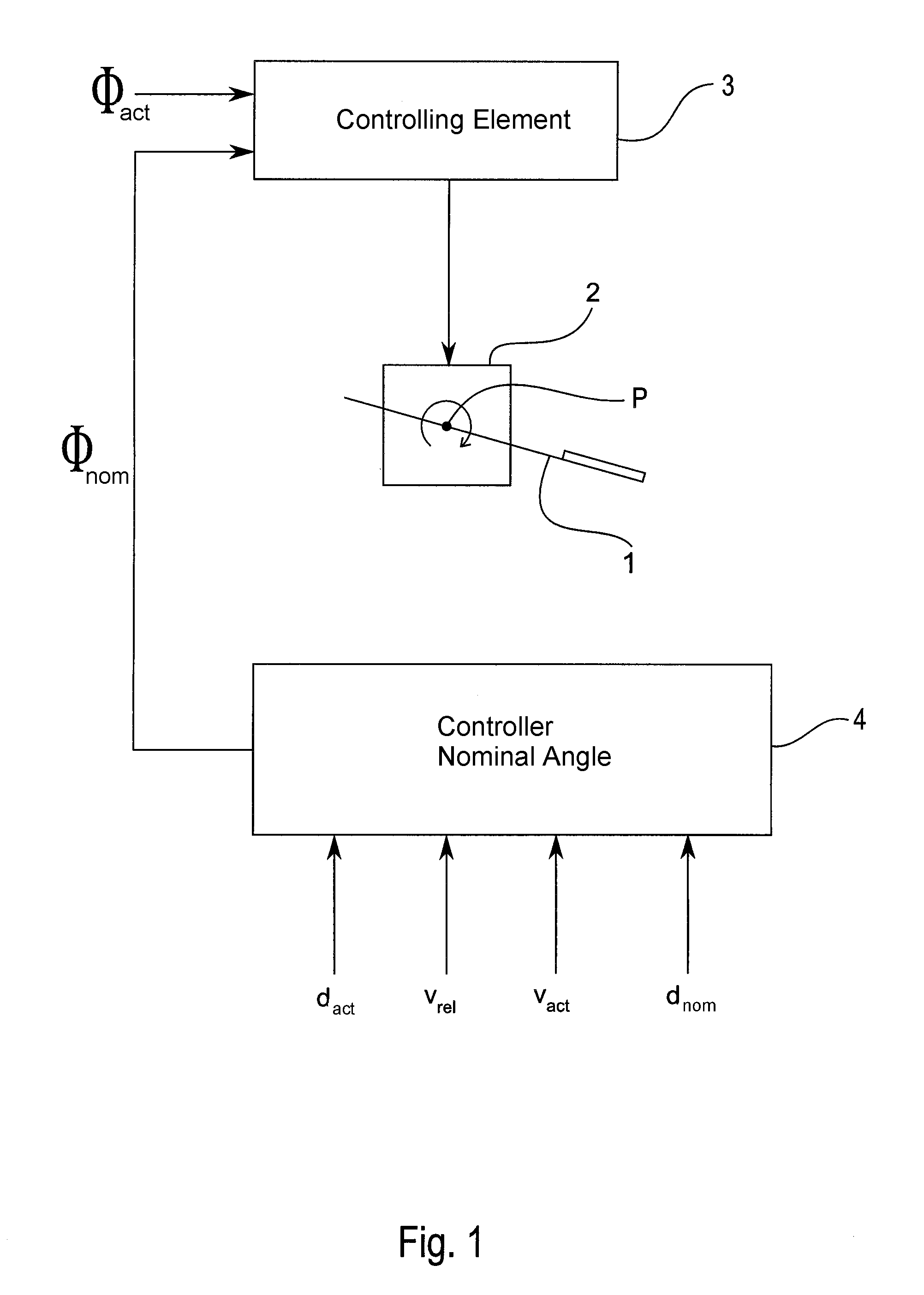
[0037]FIG. 1 shows a block diagram of a control system according to an embodiment of the invention. In the illustrated embodiment, the accelerator device 1 is an accelerator pedal as is used, for example, in cars and trucks. The accelerator pedal shown is a so-called suspended accelerator pedal unit. In principle, the method described here can, however, also be applied to so-called stationary accelerator pedal units or twist-grip throttles.

[0038]FIG. 2 is a schematic view of an accelerator device, on which the method according to the invention can be performed. The accelerator device 1 shown in FIG. 2 is an accelerator pedal as used, for example, in cars or trucks. A pedal pad 5 is rotatably supported at a pivot point P via a pedal lever 6. The pedal lever 6 can be deflected downwards by applying pressure to the pedal...


PUM


Abstract

A driver of a vehicle applies an actuation force to an accelerator device such as an accelerator pedal or a twist-grip throttle of the vehicle to deflect the accelerator device to an actual deflection angle (φact), which is detected. A restoring force acts on the accelerator device opposite the actuation force. An electronic controller determines a nominal deflection angle (φnom) to which the accelerator device shall be deflected, based on inputs such as an actual speed of the subject vehicle, a relative speed of the subject vehicle relative to a leading vehicle driving ahead of the subject vehicle, an actual distance of the subject vehicle to the leading vehicle, and a nominal distance at which the subject vehicle shall follow the leading vehicle. The restoring force on the accelerator device is modulated as a function of the difference between the actual deflection angle (φact) and the nominal deflection angle (φnom).

Description

CROSS-REFERENCE TO RELATED APPLICATIONS[0001]This application is a Continuation-In-Part (CIP) under 35 USC 111(a) and 120 of PCT International Application PCT / DE2014 / 200281 filed on Jun. 25, 2014. Through the PCT application, the present application also claims priority under 35 USC 119 of German Patent Application DE 10 2013 213 050.3 filed on Jul. 4, 2013. The entire disclosures of the priority application and the PCT application are incorporated herein by reference.FIELD OF THE INVENTION[0002]The invention relates to a controller, a control system and a method of controlling the restoring force of an accelerator device for motor vehicles. An accelerator device may, for example, be an accelerator pedal, as used in cars or trucks, or a twist-grip throttle as used, for example, on motorcycles or quad bikes or ATVs.BACKGROUND INFORMATION[0003]In order to actuate such an accelerator device, an actuation force generally has to be applied to the accelerator device. For example, an accel...

Claims


Application Information

Patent Timeline
Patent Type & Authority Applications(United States)
IPC IPC(8): B60K31/02
CPCB60K31/02B60W50/16B60K26/021B60W30/16B60K2026/023B60W2050/0009B60W2520/10B60W2554/804B60W2554/801B60W2540/10B60W2050/0012
Inventor DREWS, FRANKLEONE, CARMELO
Owner CONTI TEMIC MICROELECTRONIC GMBH
Why Eureka
Try Eureka