System comprising a pivotable armrest and a pendulum element

a technology of pendulum element and pivotable armrest, which is applied in the direction of armrests, vehicle components, vehicle arrangements, etc., can solve the problems of increased risk of injury to passengers and the pivoting of the armrest, and achieve the effect of not impairing the functionality and the operation of the pivotable armres

Active Publication Date: 2019-01-22
ADIENT US LLC
View PDF10 Cites 1 Cited by
  • Summary
  • Abstract
  • Description
  • Claims
  • Application Information

AI Technical Summary

Benefits of technology

[0004]It is an object of the present invention to provide a system by way of which, in an accident situation, the pivotable armrest is prevented from pivoting in uncontrolled fashion out of a stowage position. Here, it is desirable for the measures implemented for this purpose to as far as possible not impair the functionality and the operation of the pivotable armrest in the normal situation, that is to say in a non-accident or non-braking situation. Furthermore, the system should return to a functional state as quickly and easily as possible after the accident or braking situation.
[0010]In a further embodiment, provision is made for the spring element to be configured such that the force acting on the system must exceed a threshold value for the pivoting of the pendulum element. A pre-requisite for the pivoting of the pendulum element into a position provided for the positive locking action, that is to say into the first position, is a force which counteracts the restoring force of the spring element and overcomes or overcompensates the restoring force. Through the selection of the spring element, in particular of the restoring force of the spring element, it is accordingly possible to define the magnitude of the force that can transfer the pendulum element into the position provided for the positive locking action. In this way, it is advantageously possible for the sensitivity of the system having the pivotable armrest and having the pendulum element to be set through the suitable selection of the spring element.
[0011]In a further embodiment, provision is made for the spring element to be articulated on the bracket means. In particular, the spring element is pivotable, at a first end, about an axis running parallel to the primary axis. In this way, it can be ensured that the maximum possible restoring force of the spring element acts on the pendulum element during the pivoting of the pendulum element. Otherwise, there would be the risk of deformation of the spring element along an undesired direction, whereby the restoring force transmissible to the pendulum element would be reduced.
[0012]In a further embodiment, provision is made for the bracket means to have a second abutment, wherein the second abutment is configured such that, during a pivoting of the pendulum element along the first direction of rotation, the positioning of the pendulum element for the positively locking interaction with the connecting element can be assisted by way of the second abutment. In particular, the second abutment is configured such that a pivoting of the pendulum element along the first direction of rotation is ended. The second abutment preferably interacts with the pendulum element in positively locking fashion along the first direction of rotation in order to end the pivoting movement. In other words: the pendulum element abuts against the second abutment and is thereby positioned for the positively locking interaction with the connecting element. In this way, it is advantageously possible to avoid a situation in which the pendulum element pivots beyond the position provided for the positive locking action and thus the positive locking cannot be ensured. By way of the second abutment, it is advantageously possible to realize a system in which the positively locking interaction of pendulum element and connecting element can be ensured if the force acting on the system is greater than a threshold value.
[0013]In a further embodiment, provision is made for the pendulum element and the connecting element to be configured such that the positively locking interaction between pendulum element and connecting element takes place along a direction running substantially perpendicular to the force direction (of the force acting on the system). In this way, it is possible to realize a system having a pivotable armrest and having a pendulum element, by way of which system the force acting on the system is channeled into the positively locking interaction of two elements along a direction running perpendicular to the force direction.
[0015]In a further embodiment, provision is made for the connecting element to have a stop element, wherein, in the usage position, the stop element interacts with a first abutment of the bracket means in positively locking fashion along the second direction of rotation. In this way, it is advantageously possible to avoid a situation in which the armrest is pivoted beyond the usage position as a result of a pivoting movement along the second direction of rotation. The first abutment is advantageously integrated into the bracket means, whereby a particularly compact system with pivotable armrest and pendulum element can be realized.

Problems solved by technology

A disadvantage of the pivotable armrests from the prior art is that, in an accident situation or during intense braking of the motor vehicle, forces can arise which cause the pivotable armrest to pivot in uncontrolled fashion out of its stowage position, whereby the risk of injury to passengers is increased.

Method used


Image

  • System comprising a pivotable armrest and a pendulum element
  • System comprising a pivotable armrest and a pendulum element

Examples


Embodiment Construction

[0031]In the various figures, identical parts are always denoted by the same reference designations, and will therefore generally also be named or mentioned in each case only once.

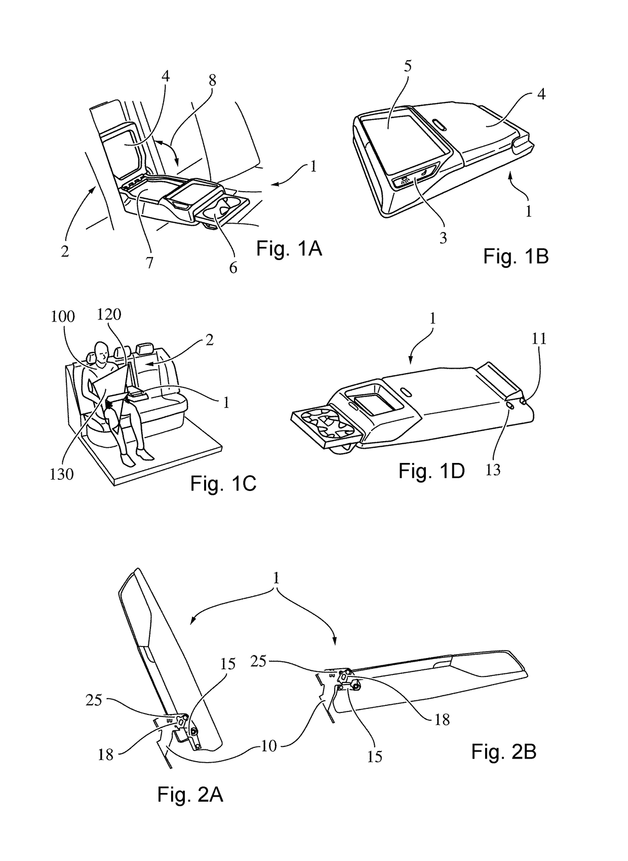
[0032]FIGS. 1A-D illustrate, in four images, examples of pivotable armrests 1 that relate to the present invention. Armrests 1 of said type are preferably integrated into a backrest 2 of a vehicle seat, in particular into the backrest 2 of a rear bench of a vehicle. Here, the armrest 1 can be reversibly transferred between a stowage position and a usage position. In the usage position, a passenger 100 of the vehicle can support his or her arm on the armrest. In particular, the armrest is encased with a cushioning such that the passenger 100 can, in the stowage position, lean his or her back against a first cushioned side of the armrest 1 and can, in the usage position, support his or her arm on a second cushioned side of the armrest 1. It is furthermore conceivable for the armrest 1 to have a stowage compa...


PUM


Abstract

A system includes a pivotable armrest (1) and a pendulum element (18). The armrest (1) is pivotably hinged on a holding device (10) around a primary axis (11). The armrest (1) is connected rotatably fixed to a connection element (15). The holding device (10) includes the pendulum element (18). The pendulum element (18) is pivotable around a secondary axis (12). The connection element (15) and the pendulum element (18) are configured such that the pendulum element (18) is pivoted into a first position when a force is exerted on the system. The pendulum element (18) pivoted in the first position interlockingly interacts with the connection element (15) in such a way that a pivoting of the connection element along a second direction of rotation (32) is countered. The first direction of rotation (31) runs counter to the second direction of rotation (32).

Description

CROSS REFERENCE TO RELATED APPLICATIONS[0001]This application is a U.S. National Phase Application of International Application PCT / EP2014 / 075324 filed Nov. 21, 2014 and claims the benefit of priority under 35 U.S.C. § 119 of German Applications 10 2013 019 719.8, filed Nov. 27, 2013, and 10 2014 206 031.1, filed Mar. 31, 2014, the entire contents of which are incorporated herein by reference.FIELD OF THE INVENTION[0002]The present invention relates to pivotable armrests. Pivotable armrests are known from the prior art and can commonly be found on vehicle seats, preferably on the backrests thereof. In particular, pivotable armrests can, when not presently being used, be transferred into a space-saving stowage position. Typically, the backrest comprises a recess into which the pivotable armrest can be pushed for stowage purposes. In the usage position, the armrest may not only serve as a support for an arm but may also further increase comfort for the passenger by way of additional s...

Claims


Application Information

Patent Timeline
Patent Type & Authority Patents(United States)
IPC IPC(8): B60N2/433B60N2/75B60N2/42
CPCB60N2/433B60N2/757B60N2/43
Inventor JAKUBEC, IVANMARTINKA, MICHALREZBARIK, MIROSLAV
Owner ADIENT US LLC
Why Eureka
Try Eureka