Control device, display device, and control method
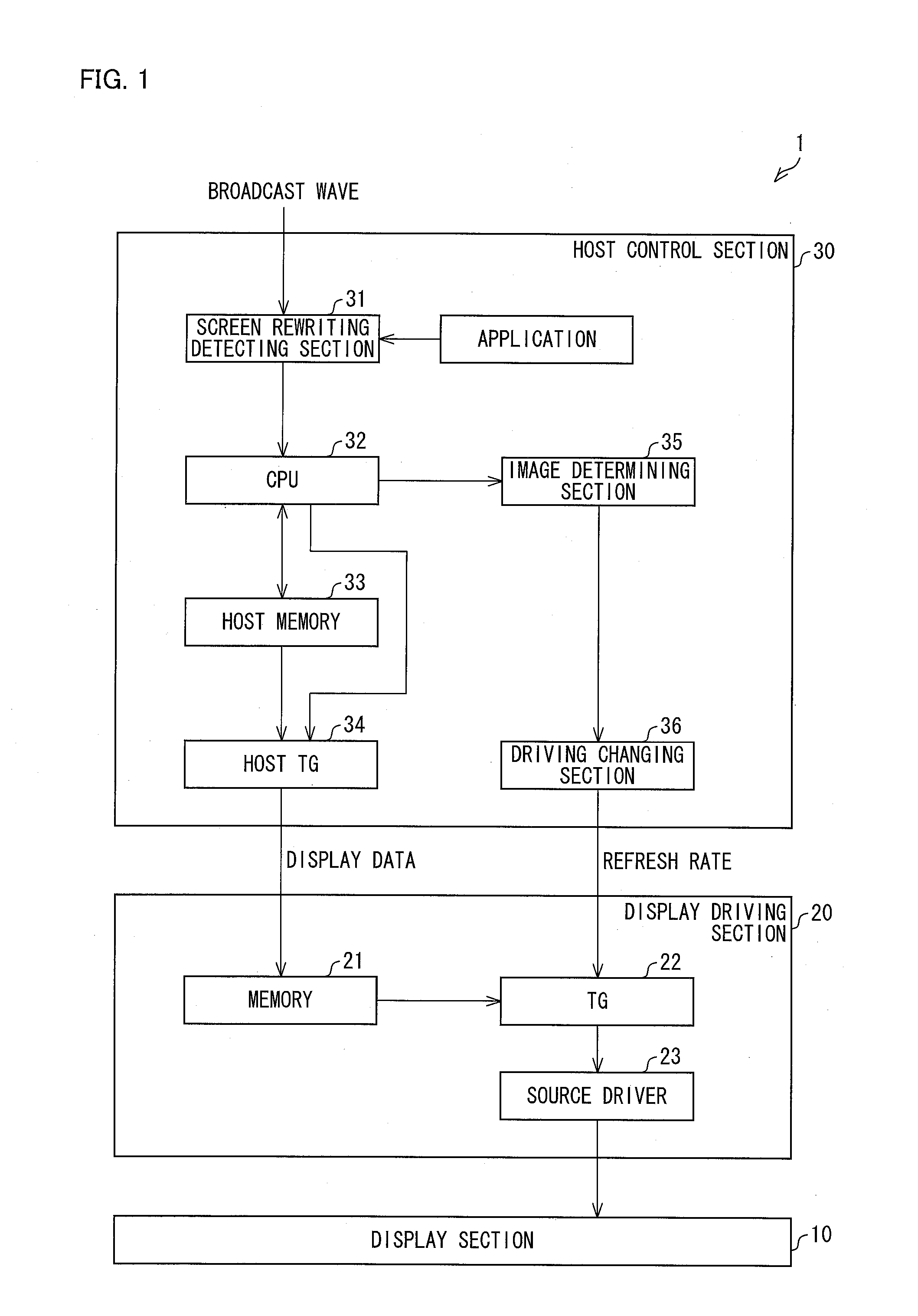
a display device and control method technology, applied in the direction of electric digital data processing, instruments, computing, etc., can solve the problems of power consumption of display devices, and achieve the effect of suppressing electric power consumption, reducing electric power consumption, and efficient achievemen
- Summary
- Abstract
- Description
- Claims
- Application Information
AI Technical Summary
Benefits of technology
Problems solved by technology
Method used
Image
Examples
embodiment 1
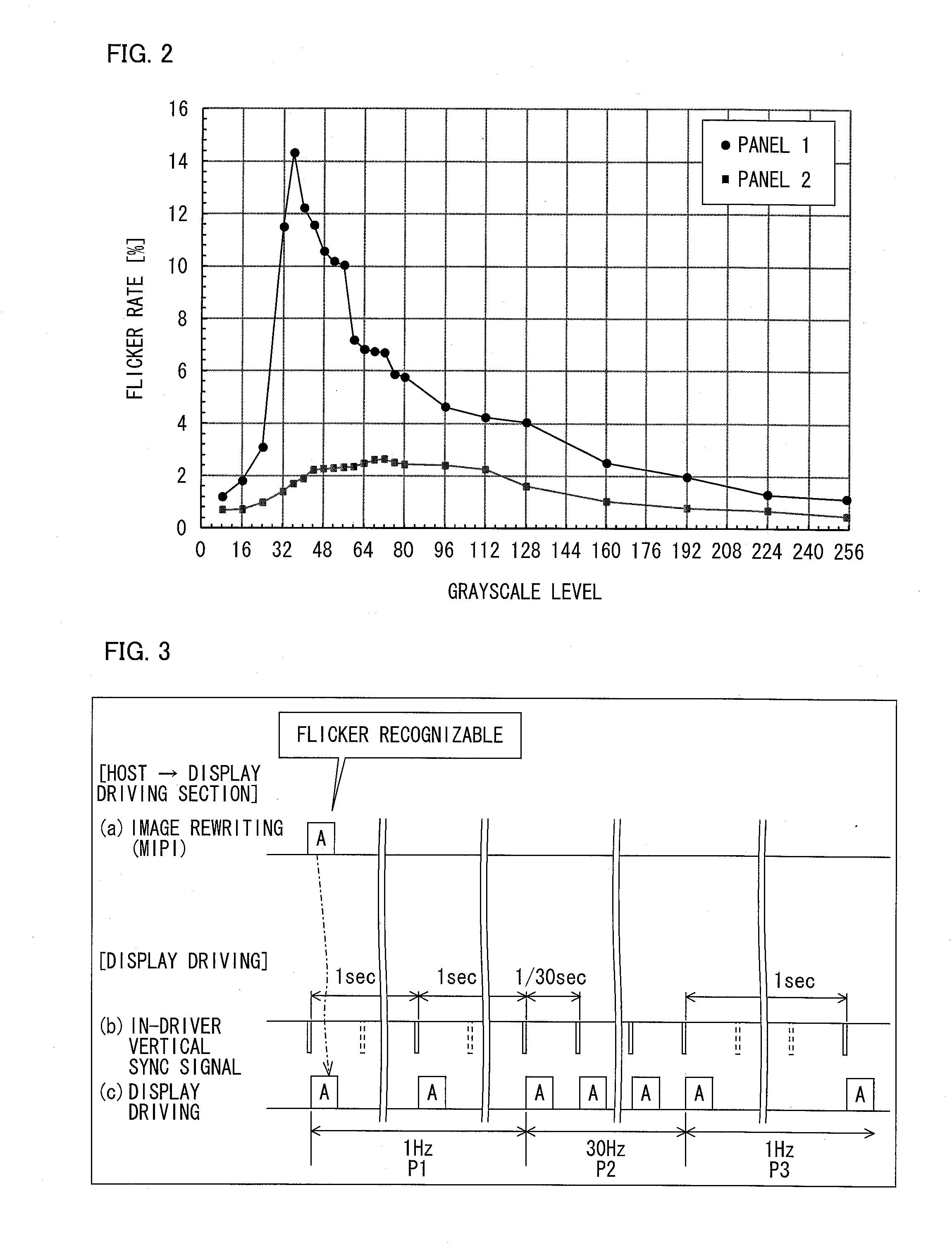
[0027]FIG. 2 is a graph showing flicker rates corresponding to respective grayscale levels at which an oxide semiconductor liquid crystal display panel is driven with a refresh rate of 1 Hz. A flicker rate indicates a degree to which flicker is recognizable, and a larger value of the flicker rate means greater recognizability of the flicker. A flicker rate of 1.5%, for example, is one indicator of whether or not flicker can be easily recognizable. In a case where the oxide semiconductor liquid crystal display panel is driven at a low refresh rate, it is a grayscale level of an image that determines whether or not flicker easily occurs. In FIG. 2, a minimum grayscale level (black) is 0, whereas a maximum grayscale level (white) is 255. Note that recognizability of flicker also varies, depending on a screen size and production process. A panel 1 is a liquid crystal display panel greater in size than a panel 2. The panel 1 and the panel 2 also differ in production process.
[0028]A respo...
embodiment 2
[0068]The following description will discuss another embodiment of the present invention. For convenience, members similar in function to those described in the foregoing embodiment will be given the same reference signs, and their description will be omitted. Embodiment 2 differs from Embodiment 1 in method of changing a refresh rate.
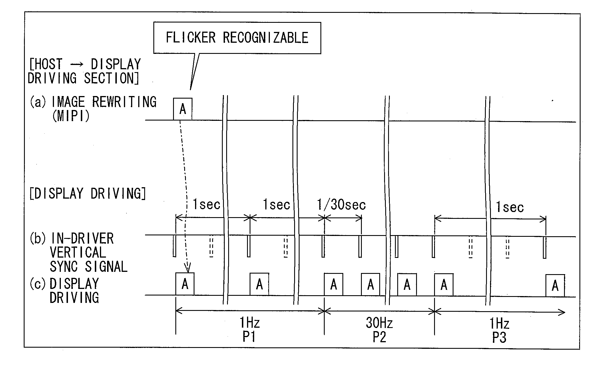
[0069]FIG. 6 is a timing chart showing how a still image A is displayed in Embodiment 2. The image A is a flickering image having a characteristic of causing flicker to be easily recognizable.
[0070]After the image A starts to be displayed, the display of the image A is refreshed every second (at 1 Hz) during a first period P1, which is the earliest period. During a second period P2, which follows the first period P1, of a display period in which the image A is displayed, the display of the image A is refreshed every 1 / 30 seconds (at 30 Hz). For example, the first period P1 lasts five seconds after the image A starts to be displayed, and the second peri...
embodiment 3
[0073]The following description will discuss a further embodiment of the present invention. For convenience, members similar in function to those described in the foregoing embodiment(s) will be given the same reference signs, and their description will be omitted.
[0074]FIG. 7 is a timing chart showing how a still image A is displayed in Embodiment 3. The image A is a flickering image having a characteristic of causing flicker to be easily recognizable.
[0075]After the image A starts to be displayed, the display of the image A is refreshed every 1 / 30 seconds (at 30 Hz) during a first period P1, which is the earliest period. During a period (second period P2), which follows the first period P1, of a display period in which the image A is displayed, the display of the image A is refreshed every second (at 1 Hz). For example, the first period P1 lasts five seconds or less after the image A starts to be displayed, and the second period P2 lasts after the first period P1 until the image A...
PUM
 Abstract
Description
Claims
Application Information
 - R&D
- Intellectual Property
- Life Sciences
- Materials
- Tech Scout
- Unparalleled Data Quality
- Higher Quality Content
- 60% Fewer Hallucinations
Browse by: Latest US Patents, China's latest patents, Technical Efficacy Thesaurus, Application Domain, Technology Topic, Popular Technical Reports.
© 2025 PatSnap. All rights reserved.Legal|Privacy policy|Modern Slavery Act Transparency Statement|Sitemap|About US| Contact US: help@patsnap.com


