
Track roller bearings with rolling elements or liners

a technology of roller bearings and roller bearings, which is applied in the direction of sliding contact bearings, transportation and packaging, static dischargers of aircraft, etc., can solve the problem that the track itself is typically not overly robust in its construction

Active Publication Date: 2016-03-24
ROLLER BEARING OF AMERICA
View PDF5 Cites 12 Cited by
  • Summary
  • Abstract
  • Description
  • Claims
  • Application Information

AI Technical Summary

Benefits of technology

The present invention relates to a track roller assembly for aircraft and an actuation system for deploying and retracting a lift assisting device for the edge of a wing. The track roller assembly includes a split inner and plural rolling elements in rolling engagement with the split inner ring and the actuation system includes a track pivotally coupled to the lift assisting device, a shaft rotationally coupled within the wing of the aircraft, and a plurality of track roller bearings guiding the track along an arcuate path. The technical effects of the invention include improved load bearing capacity, reduced wear and tear, reduced maintenance costs, and improved reliability of the track roller assembly and the actuation system for the lift assisting device.

Problems solved by technology

Since the tracks themselves are typically not overly robust in their construction, multiple load conditions may be realized by the track roller bearings.

Method used


Image

  • Track roller bearings with rolling elements or liners
  • Track roller bearings with rolling elements or liners
  • Track roller bearings with rolling elements or liners

Examples


Embodiment Construction

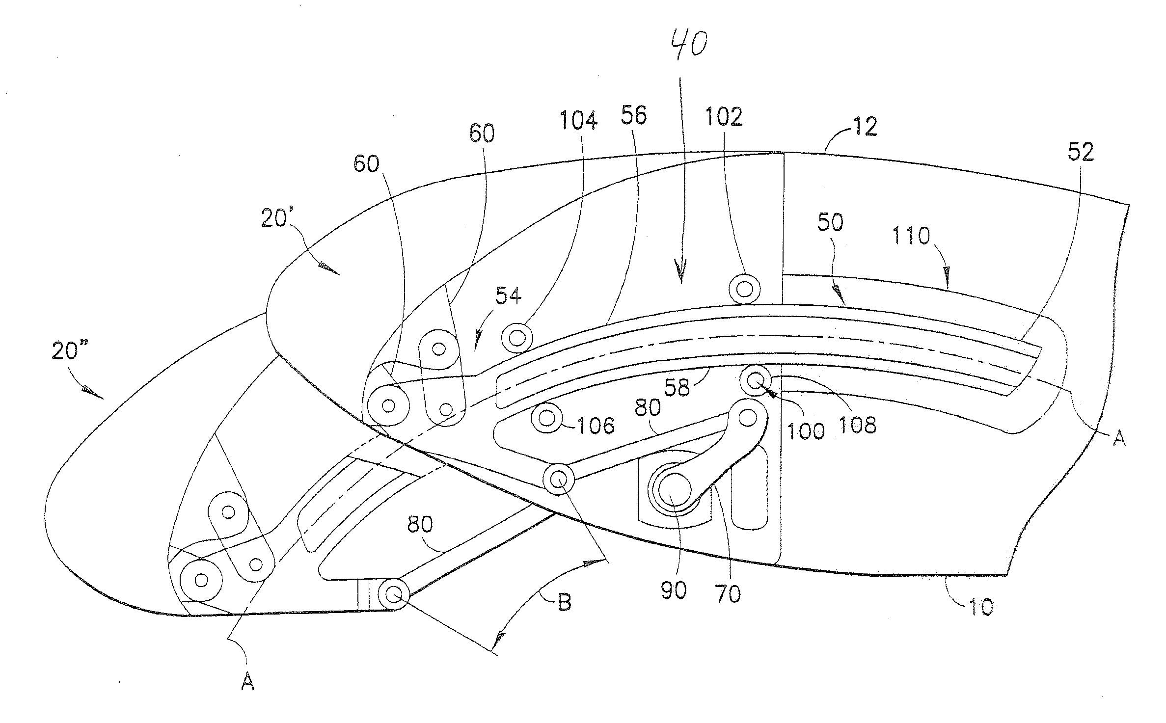
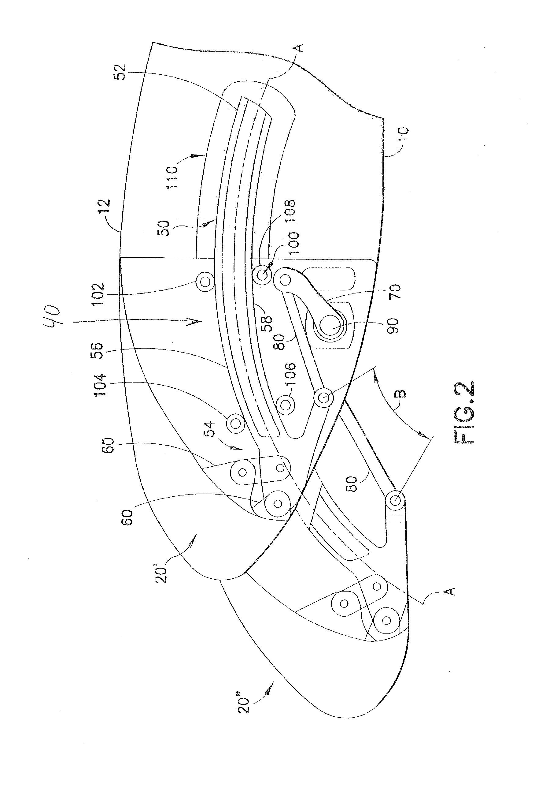
[0029]FIG. 1 provides a plan view of a leading edge section 12 of a wing 10 of an aircraft 8. The aircraft 8 is, for example, an aircraft other than a Boeing® aircraft such as, for example, an Airbus A-350 aircraft, an Airbus A-320 aircraft, an Airbus A320Neo aircraft, an Airbus A330 aircraft, an Airbus A330Neo aircraft, an Airbus A321 aircraft, an Airbus A340 aircraft, or an Airbus A380 aircraft.

[0030]One of Airbus's® is known as the Airbus® and A-350 ® aircraft. Airbus® and A-350 ® are registered trademarks of Airbus Corporation, having numerous registered trademarks therefor. The Airbus® and A-350 ® aircraft is defined by a wing planform—with a 64.7-meter wingspan, a total area of 442 square meters, and high swept leading edge. The Airbus® and A-350 ® aircraft includes a drop-hinge linkage mechanism to improve wing flap deployment kinetics, along with the introduction of a downwards movement for the upper wing spoilers to fill the gaps that occur when flaps are extended. In addit...


PUM


Abstract

A track roller assembly includes a split inner ring, a split outer ring, a one piece inner ring and / or a one piece outer ring and a liner or plurality of rolling elements engaging therewith, the track roller assembly being disposed in a structure of an Airbus A-350 aircraft, an Airbus A-320 aircraft, an Airbus A320Neo aircraft, an Airbus A330 aircraft, an Airbus A330Neo aircraft, an Airbus A321 aircraft, an Airbus A340 aircraft, and an Airbus A380 aircraft.

Description

CROSS REFERENCE TO RELATED APPLICATIONS[0001]This application: 1) claims the benefit of U.S. Provisional Application No. 62 / 088,042, filed Dec. 5, 2014 and U.S. Provisional Application No. 62 / 152,448 filed Apr. 24, 2015, which are incorporated herein by reference in their entirety; 2) is a continuation in part of and claims priority benefit under 35 U.S.C. §120 to U.S. patent application Ser. No. 14 / 287,572, filed May 27, 2014 which is a continuation in part of and claims priority benefit under 35 U.S.C. §120 to U.S. patent application Ser. No. 13 / 940,305, filed Jul. 12, 2013, which is a continuation in part of and claims priority benefit under 35 U.S.C. §120 to U.S. patent application Ser. No. 13 / 719,541, filed Dec. 19, 2012 which is a continuation in part of and claims priority benefit under 35 U.S.C. §120 to U.S. patent application Ser. No. 13 / 114,099, filed May 24, 2011 and issued as U.S. Pat. No. 8,387,924 issued on Mar. 5, 2013, which is a divisional application of and claims ...

Claims


Application Information

Patent Timeline
IPC IPC(8): B64C13/28B64C9/26F16C33/60
CPCB64C13/28B64C9/26F16C33/60B64C9/02B64C9/22B64D45/02F16C11/02F16C13/006F16C17/10F16C19/48F16C23/041F16C29/045F16C33/74F16C33/7886F16C2326/43Y02T50/40
Inventor COWLES, JR., JOHN, H.PHOENIX, JAYFREDERICKSEN, ARNOLD, E.
Owner ROLLER BEARING OF AMERICA
Learn More