
System for monitoring temperature of electrical conductor

a technology for monitoring the temperature of electrical conductors and conductors, which is applied in the direction of instruments, heat measurement, measurement devices, etc., can solve the problem of not being able to monitor the temperature of on-line electrical conductors, and achieve the effect of long usage lifetime and more reliabl

Active Publication Date: 2016-03-17
3M INNOVATIVE PROPERTIES CO
View PDF0 Cites 20 Cited by
  • Summary
  • Abstract
  • Description
  • Claims
  • Application Information

AI Technical Summary

Benefits of technology

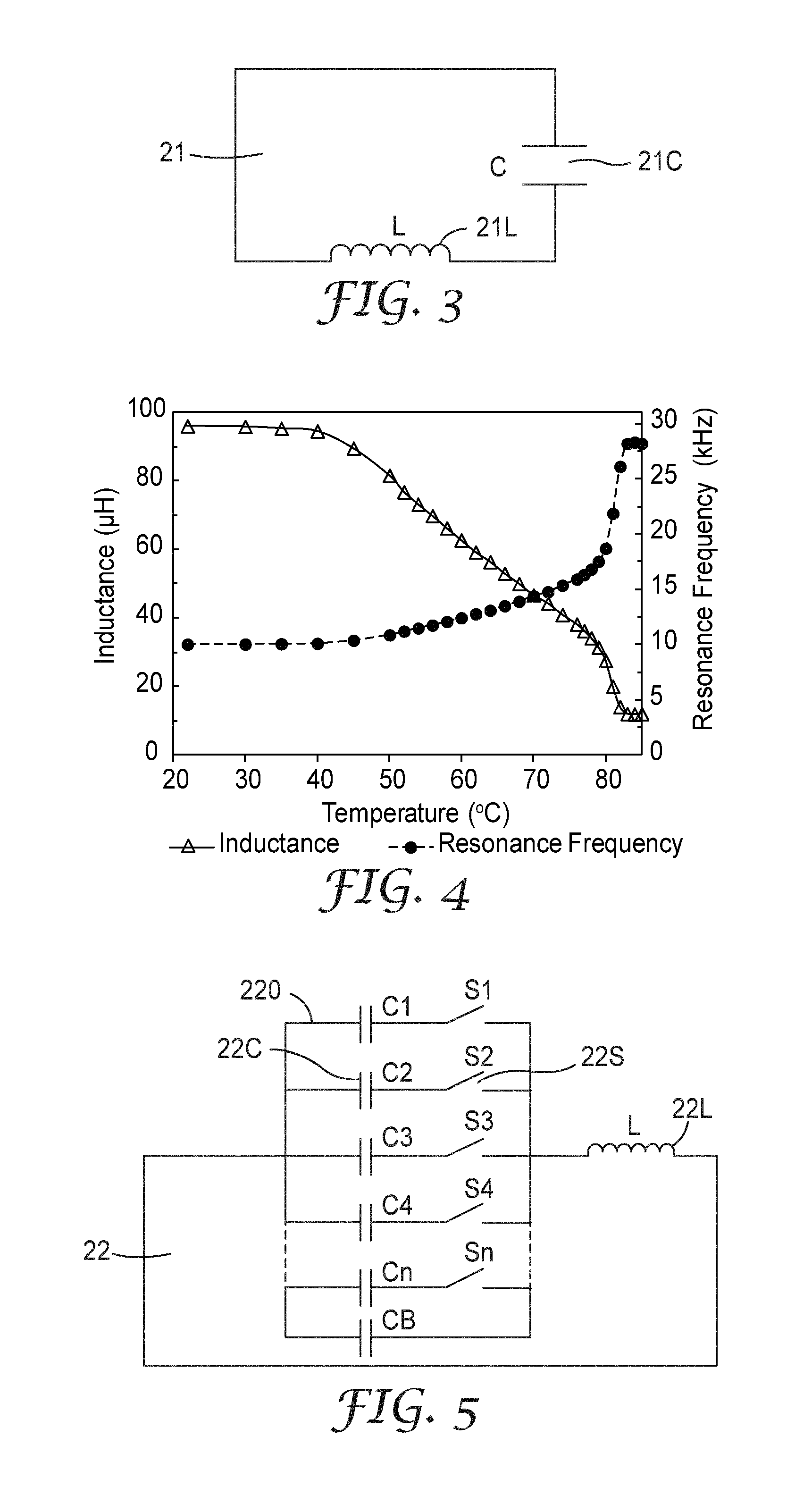
This patent is about a way to check the temperature of an electrical conductor by detecting other parameters like the resonance frequency and Q value of a passive inductive unit. This approach is different from existing solutions that use temperature sensors mounted on the surface of the power cable to estimate the temperature at the conductor. This method is more reliable with a long lifespan, because the passive inductive unit doesn't need electrical power and consists of long-lasting passive electric elements.

Problems solved by technology

If the temperatures of the cable splices or the junctions were to increase beyond that, it could be an indication that something may be wrong in this power distribution system.
Therefore, it is not easy to monitor the temperature of the on-line electrical conductor, for example, directly at the cable splices or the junctions.

Method used


Image

  • System for monitoring temperature of electrical conductor
  • System for monitoring temperature of electrical conductor
  • System for monitoring temperature of electrical conductor

Examples


Embodiment Construction

[0034]Exemplary embodiments of the present disclosure will be described hereinafter in detail with reference to the attached drawings, wherein the like reference numerals refer to the like elements. The present disclosure may, however, be embodied in many different forms and should not be construed as being limited to the embodiment set forth herein; rather, these embodiments are provided so that the present disclosure will be thorough and complete, and will fully convey the concept of the disclosure to those skilled in the art.

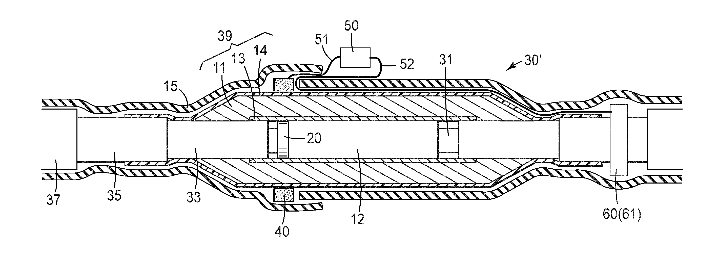
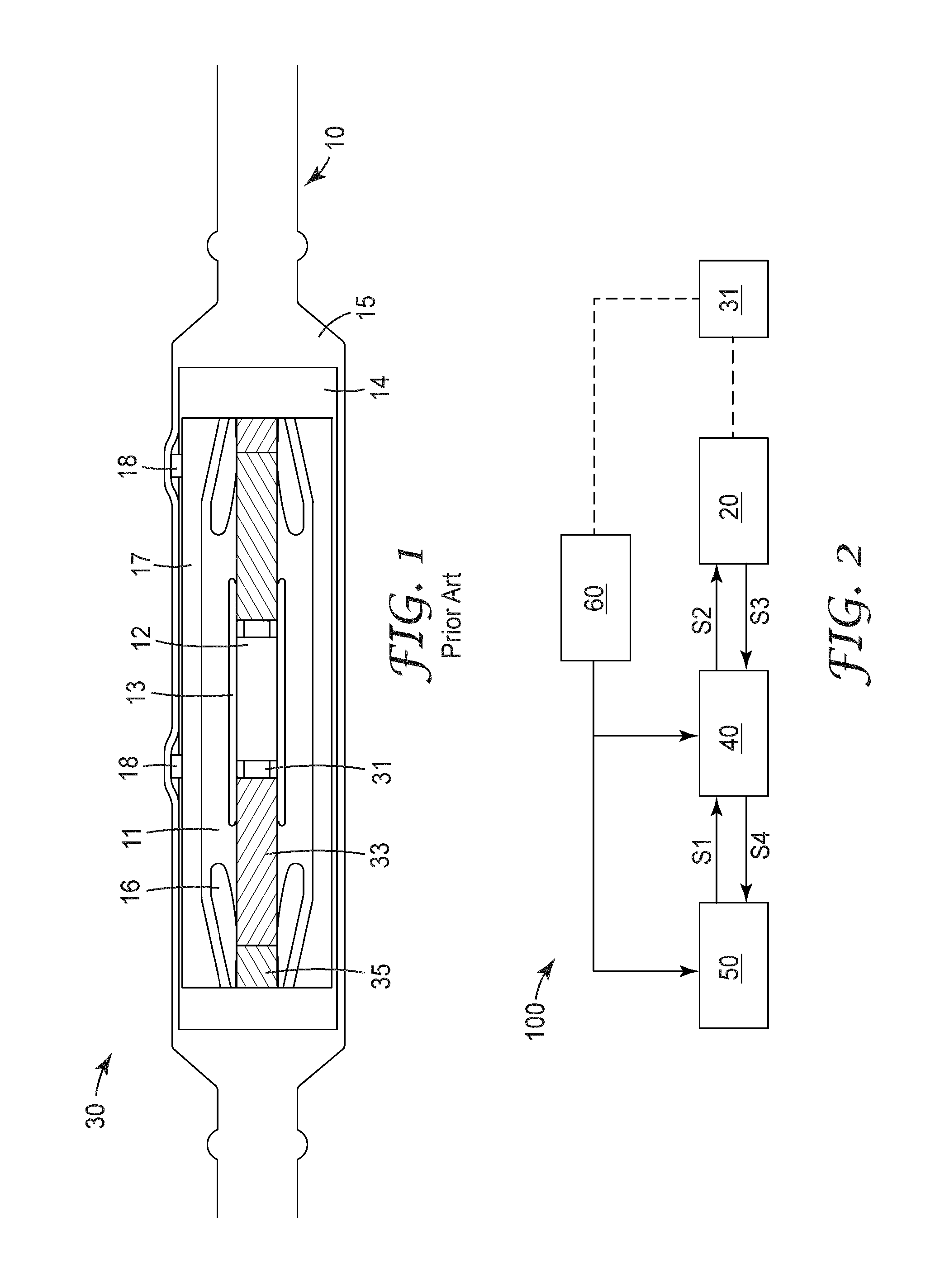
[0035]The present disclosure provides embodiments of systems for monitoring a temperature of an electrical conductor of an electrical cable, for example, at a cable splice or junction. In some embodiments, such system and method are capable of remotely monitoring the temperature at the conductor within the cable. As mentioned above, cable splices or junctions may have the weakest current carrying capacity in a high voltage power distribution system and may ha...


PUM

PropertyMeasurementUnit
temperaturesaaaaaaaaaa
constant capacitanceaaaaaaaaaa
Curie temperatureaaaaaaaaaa

Abstract

A system for monitoring temperature of an electrical conductor (31) enclosed in at least a (semi)conductive layer (13) comprising: a passive inductive unit (20), and a transceiver unit (40) and a control unit (50). The passive inductive unit (20) includes at least one temperature sensitive component and is configured to have a resonance frequency and / or Q value that vary with temperature of the electrical conductor (31). The transceiver unit (40) is configured to be electromagnetically coupled to the passive inductive unit (20) and to send out a signal representing the resonance frequency and / or Q value of the passive inductive unit (20). The transceiver unit (40) is further configured to communicate with the control unit (50) which ascertains the signal representing one or both of the resonance frequency and Q value, and which determines a value of the temperature of the electrical conductor (31) based on the ascertained signal representing one or both of the resonance frequency and Q value.

Description

FIELD OF THE INVENTION[0001]The present invention generally relates to systems for monitoring temperature of an electrical conductor, and in particular, to systems for monitoring temperature of an electrical conductor enclosed in at least a (semi)conductive layer, for example, an electrical conductor of an electrical power cable in a high voltage power distribution system.BACKGROUND OF THE INVENTION[0002]High voltage power distribution systems play an important role in modern society. Safety and security are always considerable factors for the “health” of such high voltage power distribution system. Accordingly, there should be a technology that enables monitoring of the “health” of the high voltage power distribution system.[0003]In a high voltage power distribution system, the temperature of conductors of electrical cables will increase as currents carried by the cables increase. Accordingly, the “health” of such system can be assessed by monitoring the temperature of the on-line ...

Claims


Application Information

Patent Timeline
Patent Type & Authority Applications(United States)
IPC IPC(8): G01K7/34G01K7/16
CPCG01K7/16G01K7/34G01K1/143G01K7/24G01K7/32
Inventor WEN, ZHIGUOHUANG, ZHENGYUAN, SIHUAJOHNSON, JUSTIN M.JESME, RONALD D.BONIFAS, ANDREW P.JOYCE, TERRENCE H.CHATTERTON, JACOB D.WANG, YINGYUYU, ZUETAO
Owner 3M INNOVATIVE PROPERTIES CO
Learn More