
Modular drilling fluid control system

a fluid control system and module technology, applied in the direction of drawing-off water installations, water supply installations, borehole/well accessories, etc., can solve the problems of increasing the design time, introducing errors into the system, and the drilling rig may not be in a favorable environment,

Inactive Publication Date: 2016-03-17
MI
View PDF1 Cites 2 Cited by
  • Summary
  • Abstract
  • Description
  • Claims
  • Application Information

AI Technical Summary

Benefits of technology

The present invention provides a drilling fluid control system with a modular subsystem that can be interchanged. This allows for easy replacement of parts that may need repair or adjustment, while still maintaining the same functions. The technical effects of this invention include improved efficiency and flexibility in maintenance and configuration of drilling fluid control systems.

Problems solved by technology

This process extends the design time and introduces errors into the system.
However, a drill rig may not be in a favorable environment which makes assembly of the subsystems difficult and cumbersome.
Additionally, on-site assembly complicates quality control and maintenance procedures.
As a result, the time required to set up a new drill rig and the costs associated with exploring a new drill site may increase dramatically.
However, the process of diagnosing the problem, repairing the component and testing the repair causes delays.
Often, the process of removing and transporting the component is burdensome.
With either situation, drilling the well may be delayed, and the cost of the well may increase.
This process may introduce errors into the system that may be costly to remedy.

Method used


Image

  • Modular drilling fluid control system
  • Modular drilling fluid control system
  • Modular drilling fluid control system

Examples


Embodiment Construction

[0020]The present invention relates to a drilling fluid control system for on-shore drilling environments having subsystem modules with standardized interfaces. As used herein, a slurry refers to a mixture of drilling fluid and solids.

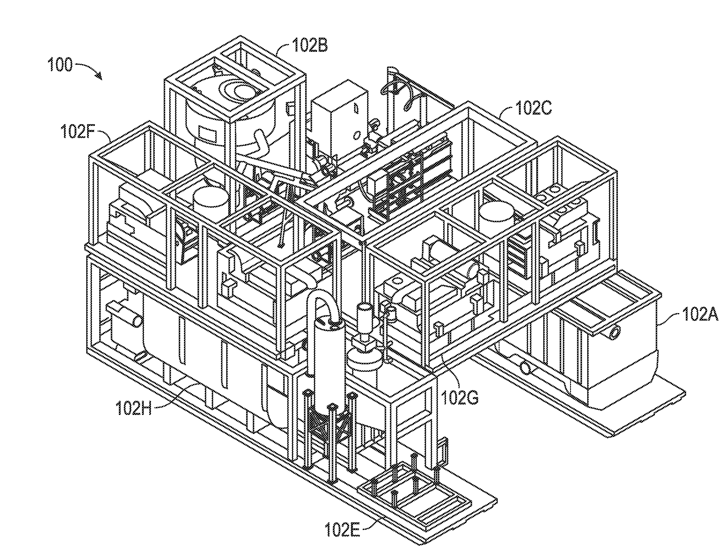
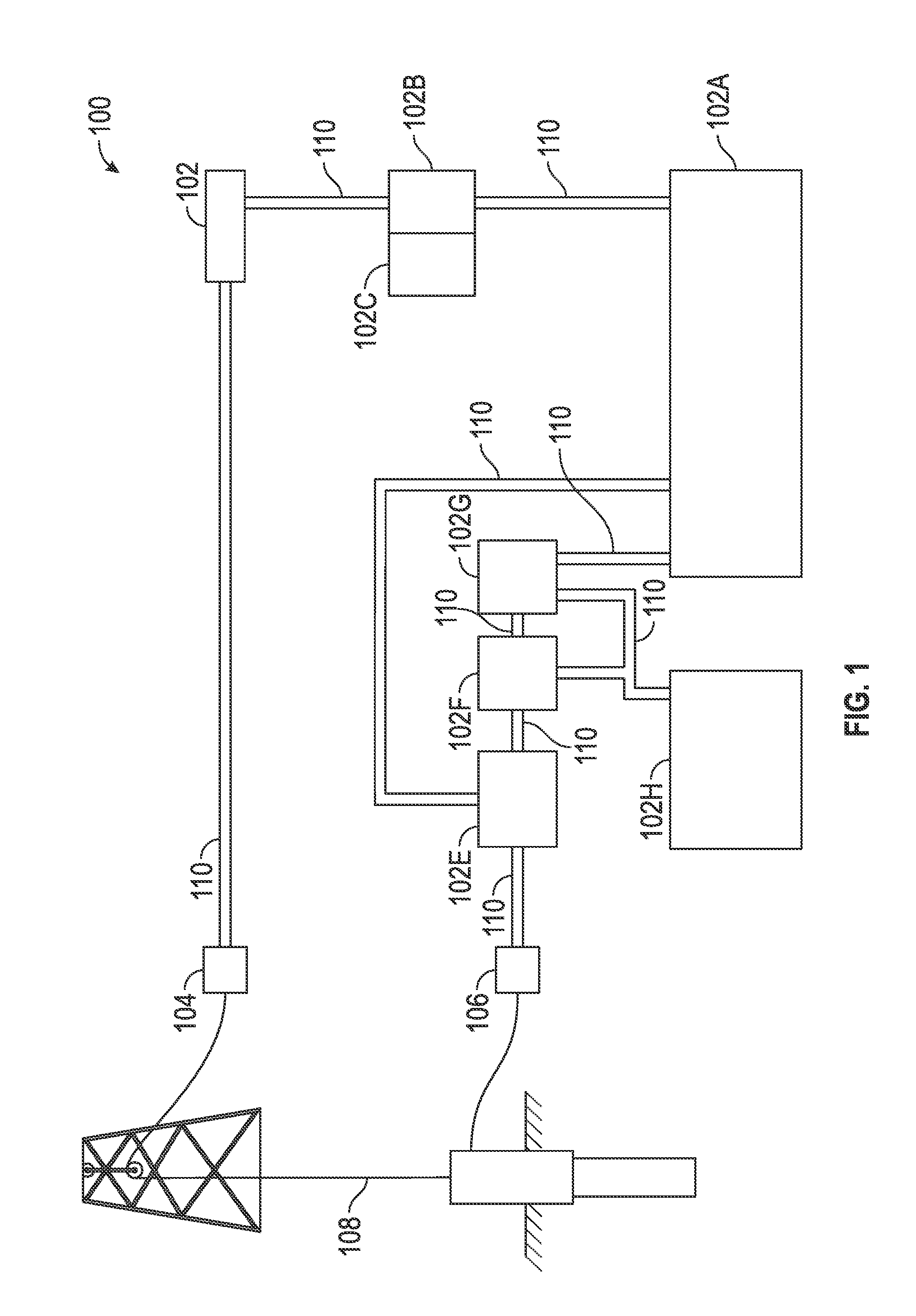
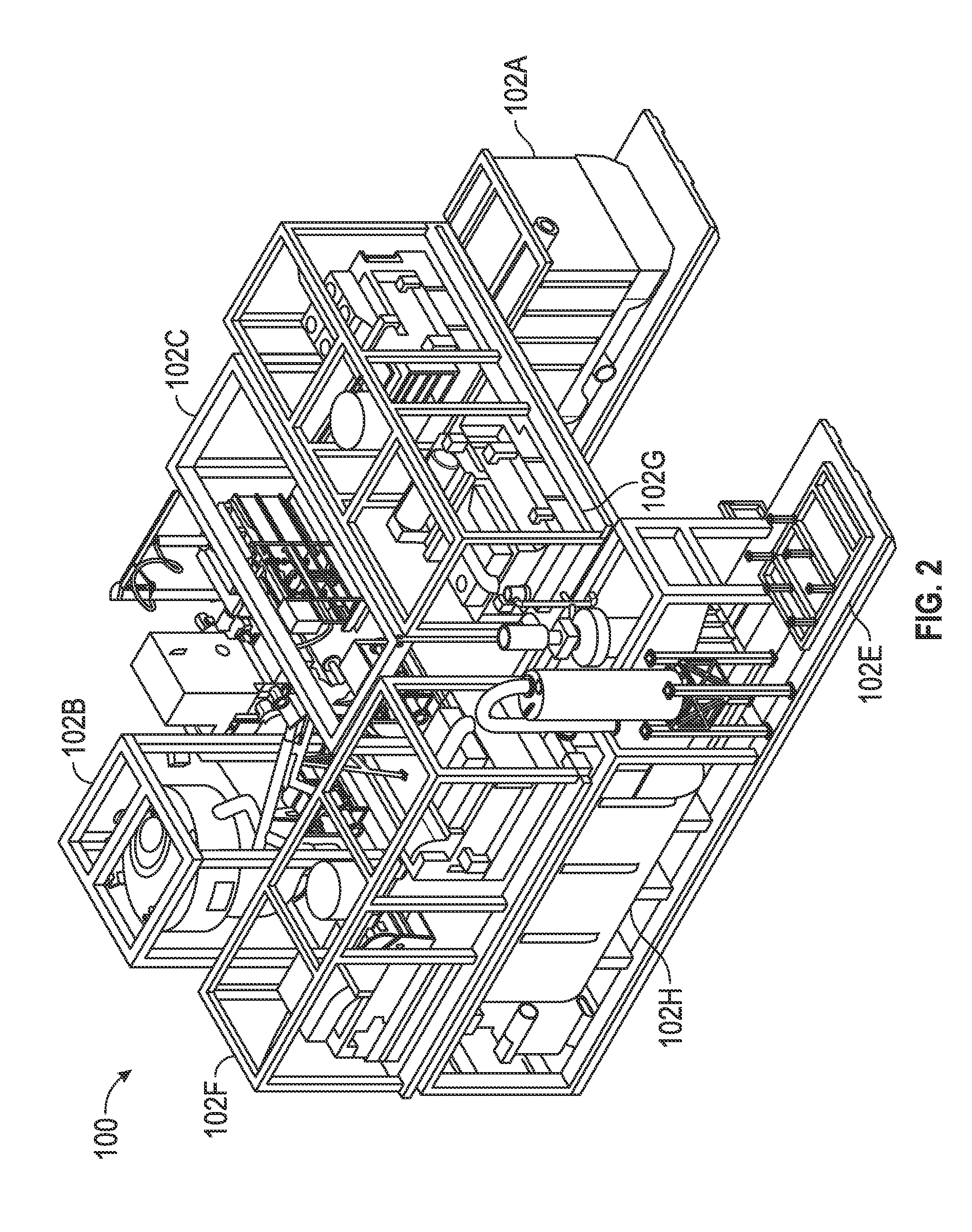
[0021]FIG. 1 and FIG. 2 generally illustrate an embodiment of a drilling fluid control system 100. The drilling fluid control system 100 may have subsystem modules 102A-102H and an output 104, an input 106 and interfacing conduit 110. The subsystem modules 102A-102H may include an active mud pit module 102A, a mud mixing module 102B, a chemical storage module 102C, a rig pump module 102D, a back pressure control module 102E, a primary shaker module 102F, a secondary shaker module 102G and / or a shaker pit module 102H. Other modules may include a dryer module (not shown) and / or an operator module (not shown). However, the present invention is not limited to the subsystem modules 102A-102H. The subsystem modules 102A-102H required for a particular embodim...


PUM


Abstract

A drilling fluid control system (100) has subsystem modules (102A-102H), an output (104) and an input (106) connected with interconnecting conduit (110). Each subsystem module (102A-102H) has a function. The subsystem modules (102A-102H) may be an active mud pit module (102A), a mud mixing module (102B), a chemical storage module (102C), a rig pump module (102D), a back pressure control module (102E), a primary shaker module (102F), a secondary shaker module (102G) and / or a shaker pit module (102H). The subsystem modules (102A-102H) with the same function may be interchanged without changing the input (102), the output (102) and the interconnecting conduit (110) of the drilling fluid control system (100). Additionally, the sub-system modules (102A-102H) are configured to fit within intermodal shipping containers.

Description

CROSS-REFERENCE TO RELATED APPLICATIONS[0001]This application claims the benefit of U.S. Provisional Patent Application No. 61 / 819,045, filed 3 May 2013 (Mar. 05, 2013), the disclosure of which is incorporated herein by reference.BACKGROUND OF THE INVENTION[0002]The present invention generally relates to drilling fluid control systems for on-shore drilling rigs. More specifically, the present invention relates to modular drilling fluid control systems for on-shore drilling environments having self-contained subsystem modules with standardized interfaces. The subsystem modules may be, for example, a drilling fluid storage module, a mud mixing module, a chemical storage module, a back pressure control module, a choke manifold module, a solids control module, a primary shaker module, a secondary shaker module, a solids dryer module, and / or a shaker pit module.[0003]Boreholes are frequently drilled into the Earth's formation to recover deposits of hydrocarbons and other desirable materi...

Claims


Application Information

Patent Timeline
IPC IPC(8): E21B21/08E21B21/06
CPCE21B21/08E21B21/06
Inventor SHERWOOD, JOE, M.
Owner MI
Learn More