Arrangement for the removable coupling of a tool with a manoeuvrable arm of a working machine

a technology of working machine and manoeuvrable arm, which is applied in the direction of couplings, manufacturing tools, mechanical apparatus, etc., can solve the problems of inability to achieve undesired locking power variations of prior art coupling arrangements, etc., to achieve simple, rapid and safe manner, increase the distance between the free end and the free end, and low additional distance

Active Publication Date: 2016-03-17
GEOBRUGG AG
View PDF4 Cites 0 Cited by
  • Summary
  • Abstract
  • Description
  • Claims
  • Application Information

AI Technical Summary

Benefits of technology

[0005]A first purpose of the present invention, therefore, is to achieve an arrangement for the removable coupling of a tool with a manoeuvrable arm of a working machine that solves the problems described above and makes it possible to allow the mounting and demounting of a tool at the arm of a working machine in a simple, rapid and safe manner. A lightweight coupling arrangement is primarily aspired to that demonstrates the absence of an intermediate piece that increases the distance between the free end of the manoeuvrable arm and the attachment of the tool. The elimination of such an intermediate piece means that the coupling arrangement can receive a low additional distance, a simplified design, with low weight and a significant saving in material consumption. Through a saving of weight, i.e. with a lower net weight of the coupling arrangement, the working machine can support heavier and thus more powerful tools at the free end of the manoeuvrable arm. In other words, a relatively small working machine can be used to work with relatively heavier, and thus more efficient, tools.

Problems solved by technology

This has not been possible with prior art coupling arrangements, in particular with the commonly occurring type that is locked by a locking mechanism that comprises a wedge and counterpiece, and where the wedge is driven into the locking mechanism by an operator by hand by means of an impact tool.
It should be understood that the locking power of the coupling arrangement with this prior art design will vary in an undesired manner.

Method used


Image

  • Arrangement for the removable coupling of a tool with a manoeuvrable arm of a working machine
  • Arrangement for the removable coupling of a tool with a manoeuvrable arm of a working machine
  • Arrangement for the removable coupling of a tool with a manoeuvrable arm of a working machine

Examples


Embodiment Construction

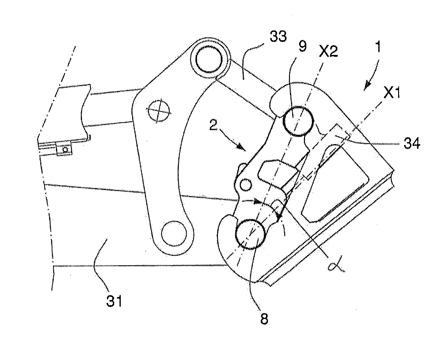
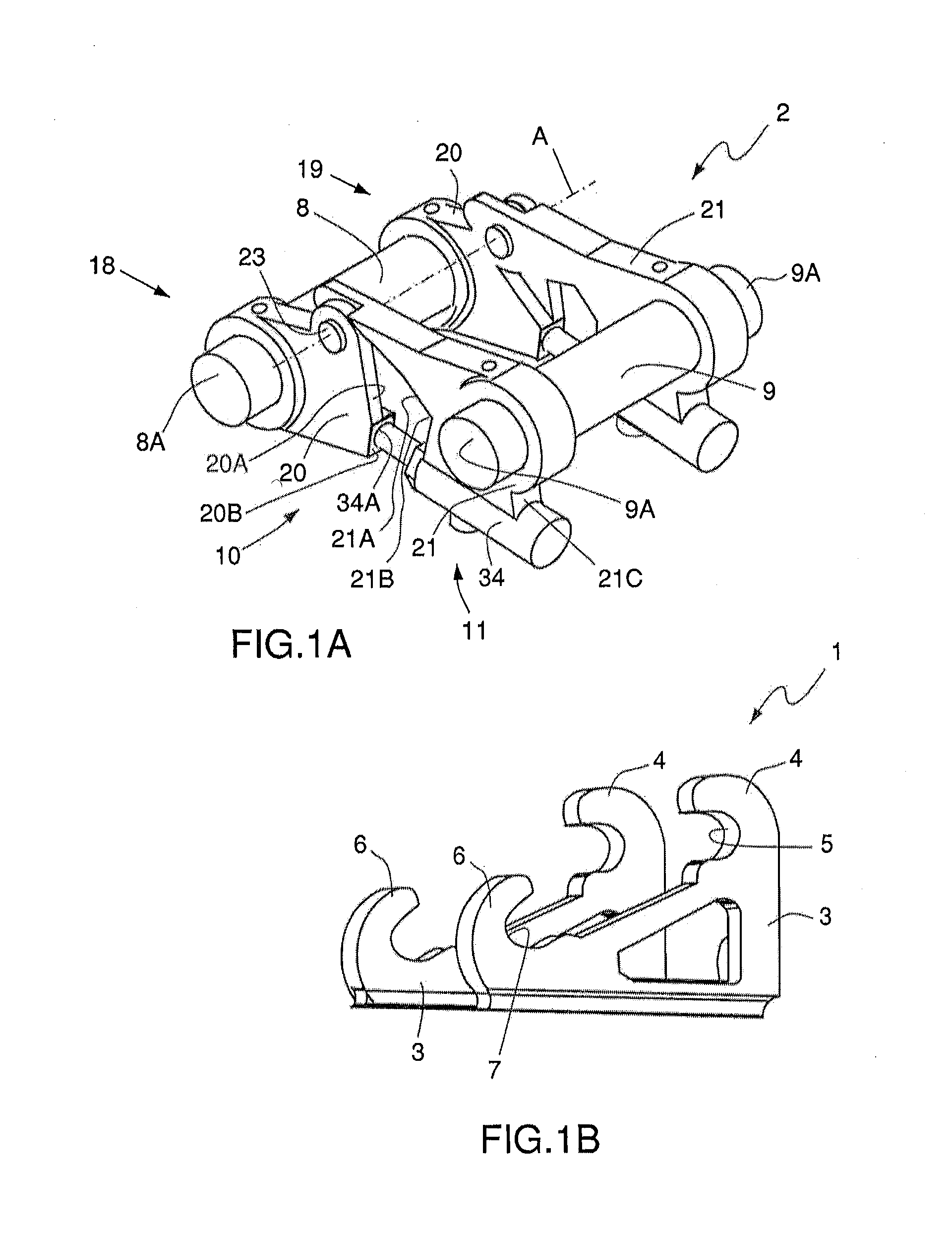
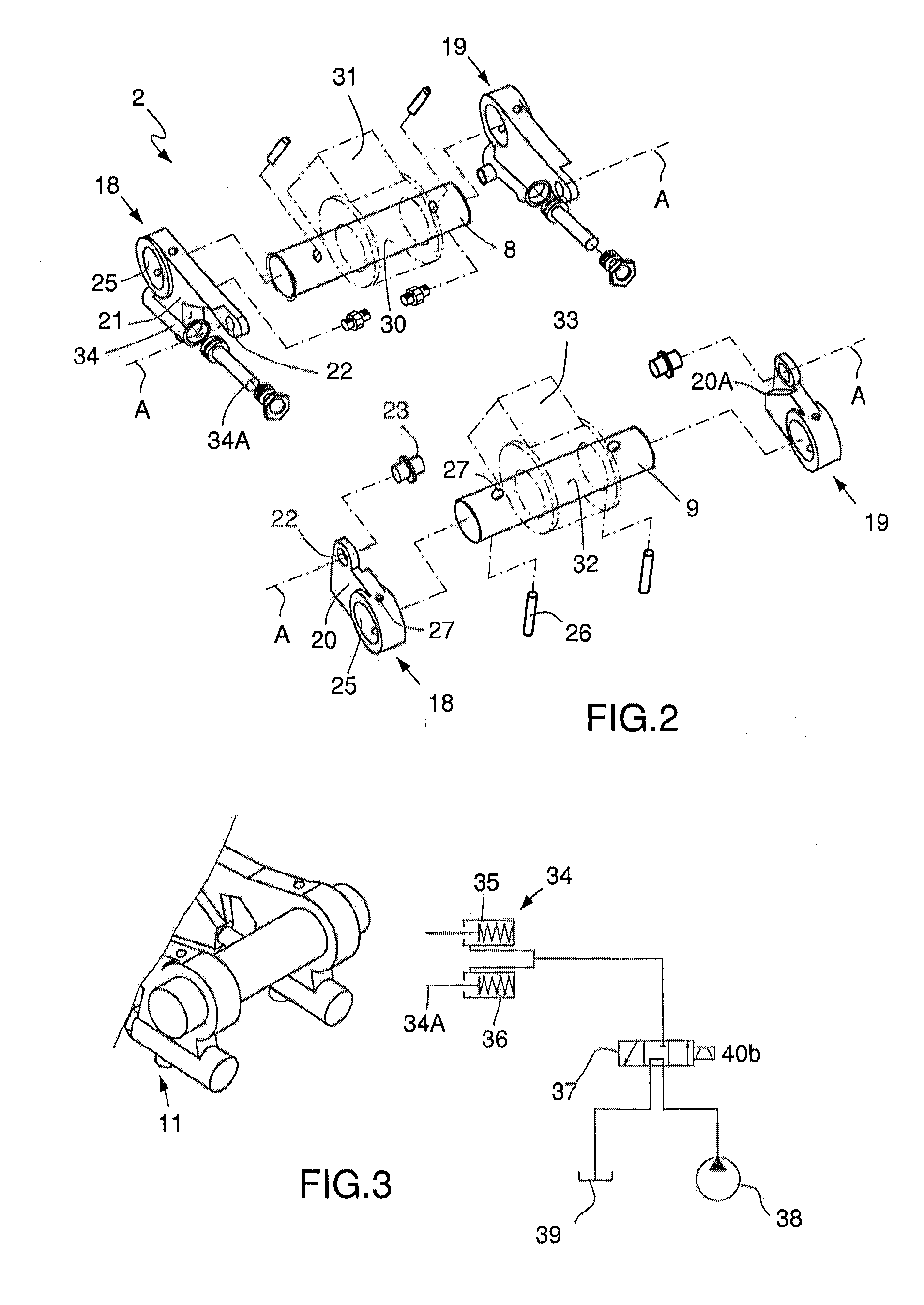
[0015]The arrangement according to the invention shown in the drawings comprises a first part 1 (FIG. 1B) that is connected to a tool and a second part 2 (FIG. 1A) that is connected to a manoeuvrable arm at a working machine. Neither the working machine nor the tool is displayed in its entirety in the drawing, since these in themselves do not constitute any part of the invention.

[0016]The part 1 (FIG. 1B) that is supported by the tool comprises two parallel side pieces 3 located at a distance from each other, each one on which demonstrates, at one of its end sections, a protrusion 4 with a U-shaped inwardly open first indentation 5, the bottom of which is semicircular with a specified radius or diameter. Each side piece 3 demonstrates at its second end section a protrusion 6 with a similar U-shaped inwardly facing second indentation 7, corresponding to that described above. The two side pieces 3 that are located pairwise in parallel are so designed that the first indentations 5 in o...


PUM


Abstract

An arrangement for removable coupling of a tool with a working machine includes a first part with opposing indentions, which is supported by the tool, and a second part that is supported by a maneuverable arm, which includes shafts to be introduced into the indentations, a lever with which the shafts can be moved away from each other, and a locking mechanism for the displacement of the shafts. One of the shafts is united at a joint with a first arm section, and another shaft is united at a joint with a second arm section. The arrangement also includes at least one knee lever joints, one of which demonstrates two levers united with the shafts.

Description

CROSS-REFERENCE TO RELATED APPLICATIONS[0001]This application claims priority to Swedish Patent Application No. SE 1451056-4 filed on Sep. 12, 2014, the disclosure of which including the specification, the drawings, and the claims is hereby incorporated by reference in its entirety.FIELD OF THE INVENTION[0002]The present invention concerns an arrangement for the removable coupling of a tool with a manoeuvrable arm of a working machine. The invention concerns also the use at a coupling arrangement of an adjustable control and actuator means that is activated by a medium under pressure and that has an inverted function.BACKGROUND OF THE INVENTION[0003]Coupling arrangements of this type for the removable coupling of a tool with a manoeuvrable arm of a working machine are previously known. One disadvantage with prior art coupling arrangements is that they are complicated and add a great deal to the distance between the end of the manoeuvrable arm end and the tool. Prior art coupling arr...

Claims


Application Information

Patent Timeline
Patent Type & Authority Applications(United States)
IPC IPC(8): E02F9/00F16C11/10
CPCF16C11/10E02F9/006E02F3/3613E02F3/3618E02F3/3622E02F3/3663E02F3/3636
Inventor HEDLUND, JAN
Owner GEOBRUGG AG
Why Eureka
Try Eureka