
Push filter with floating key lock

a technology of push filter and key lock, which is applied in the direction of filtration separation, membrane technology, separation process, etc., can solve the problems of difficult replacement of filter and awkward access

Active Publication Date: 2016-03-17
KX TECH LLC (DW US)
View PDF5 Cites 15 Cited by
  • Summary
  • Abstract
  • Description
  • Claims
  • Application Information

AI Technical Summary

Benefits of technology

The present invention provides a filter housing apparatus with a simple locking mechanism for easy replacement and removal. This apparatus allows for keyed identification of the filter.

Problems solved by technology

Although these patents show filters for water filtration, the filters are difficult to replace owing to their design and placement.
The filter access is coplanar with the refrigerator wall and forces an awkward access to the filter cartridge.

Method used


Image

  • Push filter with floating key lock
  • Push filter with floating key lock
  • Push filter with floating key lock

Examples


Embodiment Construction

)

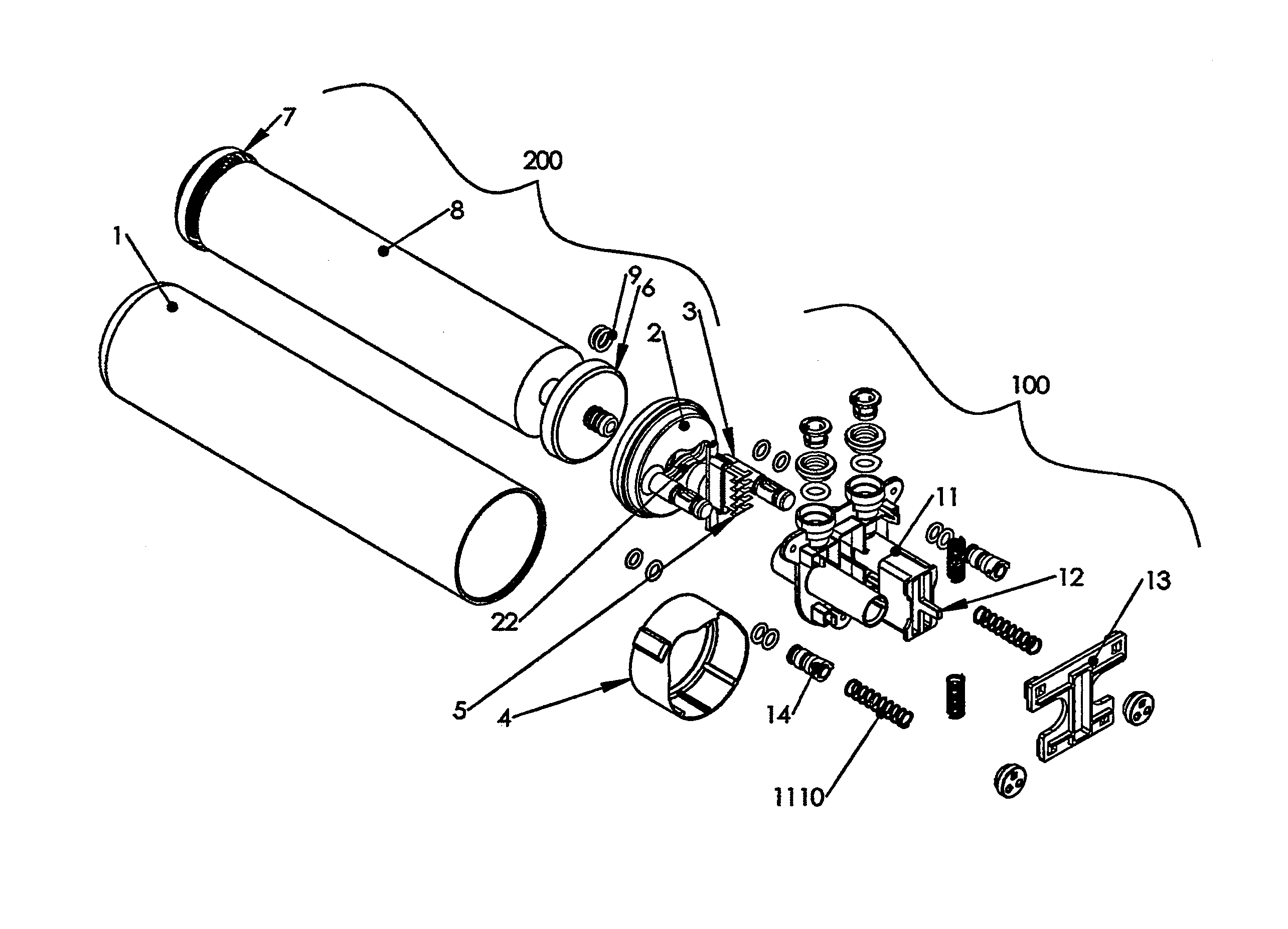
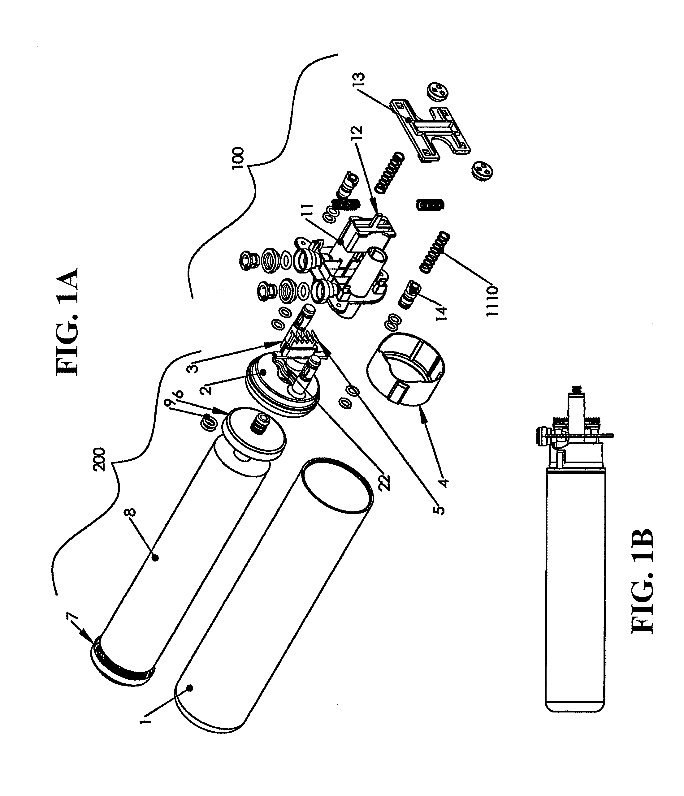
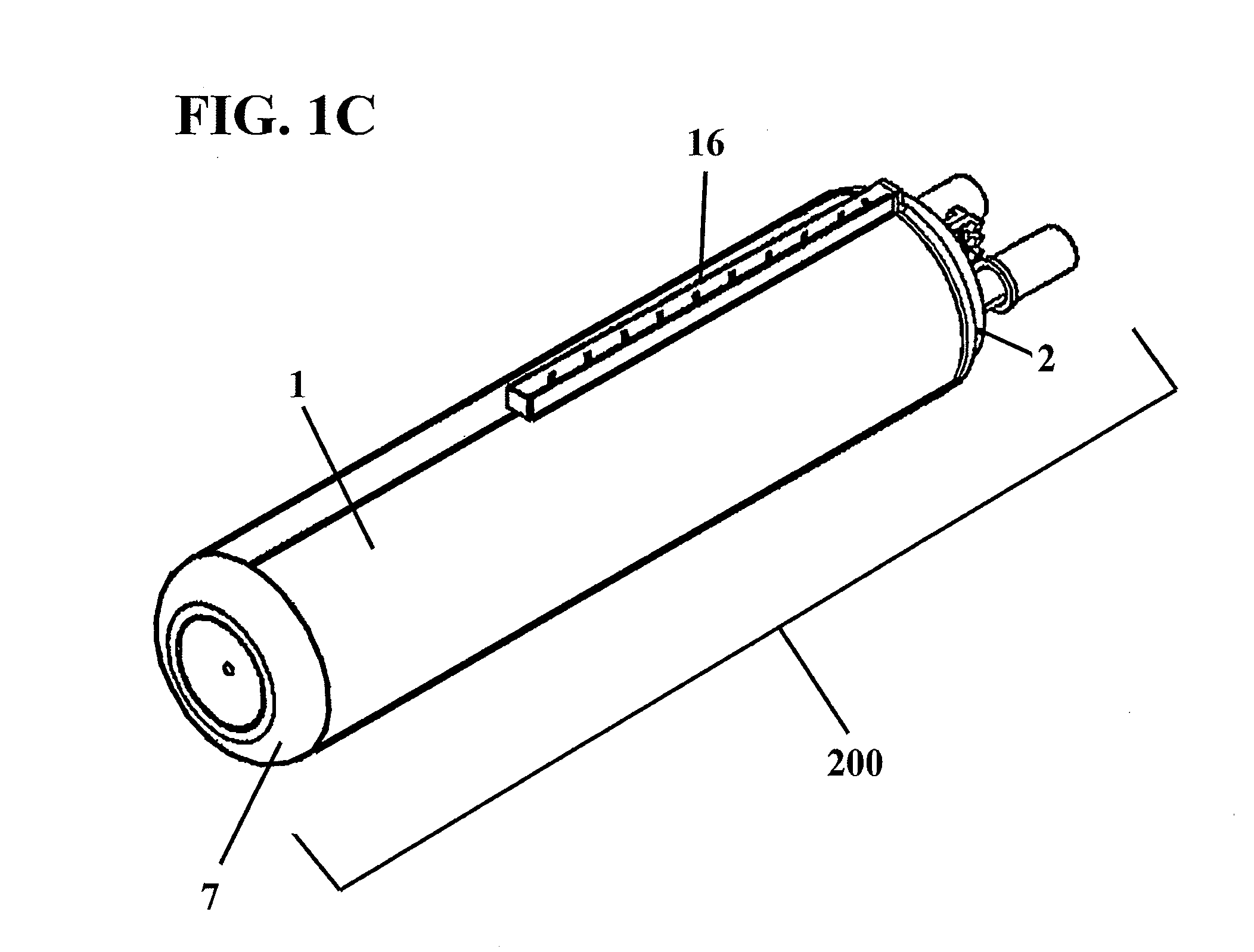
[0078]In describing the preferred embodiment of the present invention, reference will be made herein to FIGS. 1 to 11 of the drawings in which like numerals refer to like features of the invention. Features of the invention are not necessarily shown to scale.

[0079]The present invention is directed to a filter housing assembly for filtration of liquids, including the interception of chemical, particulate, and / or microbiological contaminants. The use of the mechanical locking assembly of the filter housing without the need for excess force and tight tolerances essential in prior art filter housings makes for easy and frequent filter changes and optimal filter performance. The filter housing assembly of the present invention provides simplified filter changes to minimize process downtime and without recourse to tools. A simple push mechanism actuates the self-driving release and change over means that hold and release the filter housing sump or filter cartridge, and provides influent ...


PUM

PropertyMeasurementUnit
forcesaaaaaaaaaa
axial forceaaaaaaaaaa
track structureaaaaaaaaaa

Abstract

A filter assembly for fluid filtration having a push-activated lock and release mechanism. A push filter design activates a floating key lock upon insertion and extraction, where the filter key may be used simultaneously as a lock and as an identifier for particular filter attributes. The filter base may be situated inline, and in fluid communication, with influent and effluent piping, such as within a refrigerator. The filter housing assembly may be attached to, and removed from, the filter base by a push-actuated release. Upon insertion, the filter key shifts the filter lock longitudinally to receive interlocking segments. Upon extraction, the same axial push shifts the filter lock further to align the interlocking fingers within gaps that allow for easy extraction. The specific key lock design allows a user to identify and match certain filter configurations received by the mechanical support, and reject other filter configurations.

Description

BACKGROUND OF THE INVENTION[0001]1. Field of the Invention[0002]This invention relates to a filtering apparatus, specifically a filter housing apparatus to facilitate easy removal and replacement of a filter housing from a mechanical support, and more specifically, to a push filter design that activates a floating key lock, where the key may be used simultaneously as a lock and as an identifier for particular filter attributes. The mechanical support may be situated inline, and in fluid communication, with influent and effluent piping, such as within a refrigerator. More specifically, the invention relates to a filter housing and mount, whereby the filter housing may be attached to, and removed from, the mount by a push-actuated release. A controlled attachment or detachment of the filter sump, containing the filter media, is activated by the axial push of the sump towards the mechanical support. The specific key lock design allows a user to identify and match certain filter configu...

Claims


Application Information

Patent Timeline
Patent Type & Authority Applications(United States)
IPC IPC(8): B01D35/14B01D35/30
CPCB01D35/30B01D35/14B01D2201/302B01D2201/4076B01D29/96B01D2201/4053B01D2201/301B01D2201/305B01D35/306B01D2201/4061
Inventor HUDA, STEPHEN P.SHERMAN, MICHAEL J.HAEHN, STEVEN J.KLIMPEL, ERIK R.
Owner KX TECH LLC (DW US)
Learn More