
Full-Wavefield Inversion Using Mirror Source-Receiver Geometry

a technology of source and receiver, applied in the field of geophysical prospecting for hydrocarbons, can solve the problems of difficult numerical simulation of free-surface multiples, generation of interface errors, and inability to accurately simulate source and receiver ghosts in synthetic data

Inactive Publication Date: 2016-03-03
BANSAL REESHIDEV +4
View PDF8 Cites 15 Cited by
  • Summary
  • Abstract
  • Description
  • Claims
  • Application Information

AI Technical Summary

Benefits of technology

The invention is a method for prospecting for oil and gas using seismic survey data. The method involves creating a computer model of the seismic environments, adding actual and simulated sources and receivers to the model, simulating the seismic data, and using the data to infer a subsurface model of velocity or other physical properties. This model is then used in prospecting for oil and gas. The invention allows for more accurate detection of oil and gas reservoirs, providing a better understanding of the subsurface and planning for resource development and production.

Problems solved by technology

The finite-difference methods [1], which are the most popular numerical scheme for solving the wave equation, suffer from the interface error generated by the misalignment between numerical grids and numerical interfaces [2].
Accurate numerical simulation of free-surface multiples is a challenging task [2].
Without the free-surface boundary condition, however, it is not possible to accurately simulate source and receiver ghosts in the synthetic data.
This approach, however, has two flaws: (1) it does not account for offset- or angle-dependent variation of source and receiver ghosts; (2) it does not accurately simulate the direct arrivals (source-to-receiver direct transmissions) which will also be present in the measured data.
Incorrect simulation of direct arrivals may lead to erroneous FWI results.
In the shallow water environments, however, direct arrivals are intermingled with the rest of the wavefields and it has not been possible to mute them without losing a significant part of the wavefield that FWI needs.

Method used


Image

  • Full-Wavefield Inversion Using Mirror Source-Receiver Geometry
  • Full-Wavefield Inversion Using Mirror Source-Receiver Geometry
  • Full-Wavefield Inversion Using Mirror Source-Receiver Geometry

Examples


Embodiment Construction

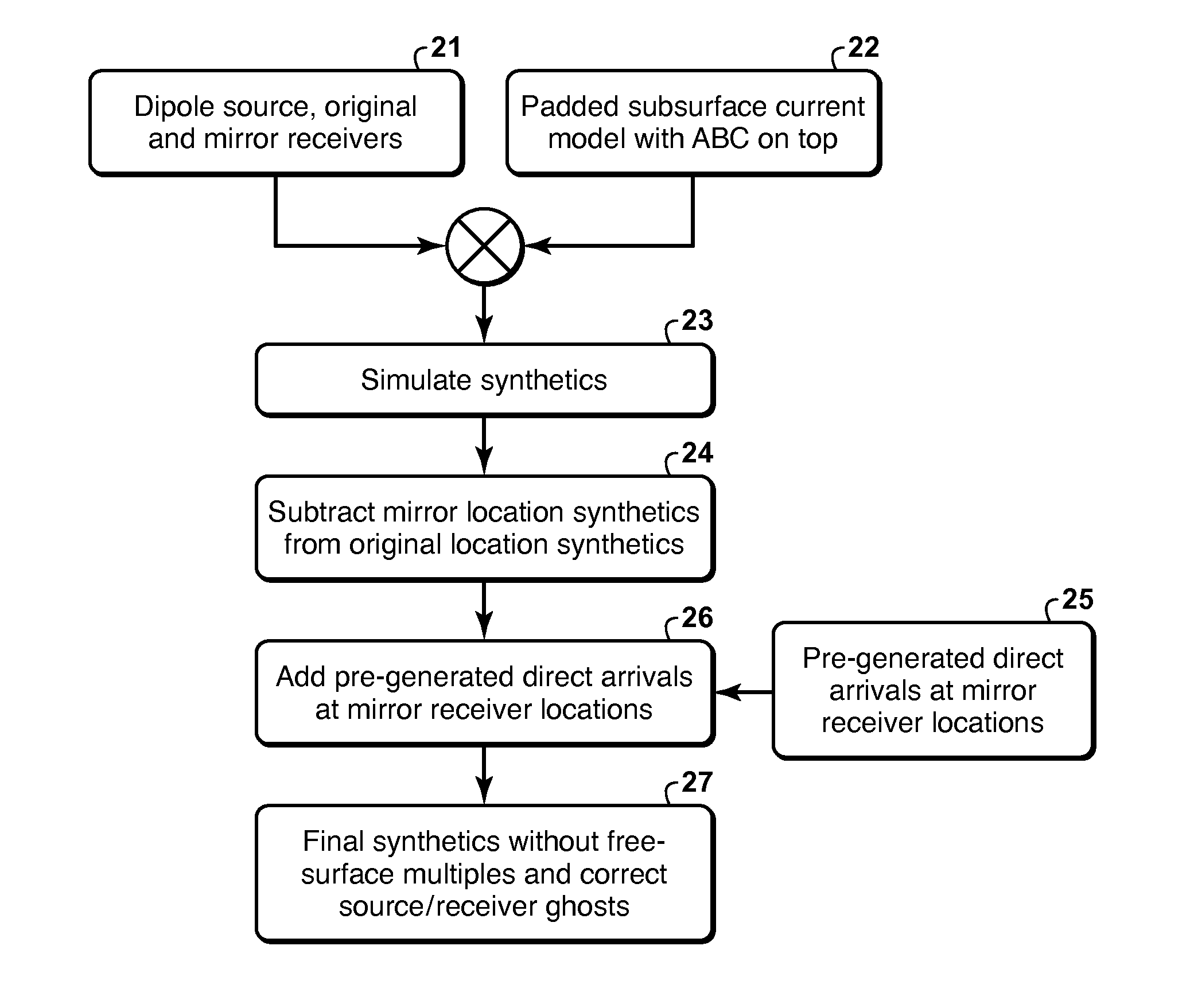
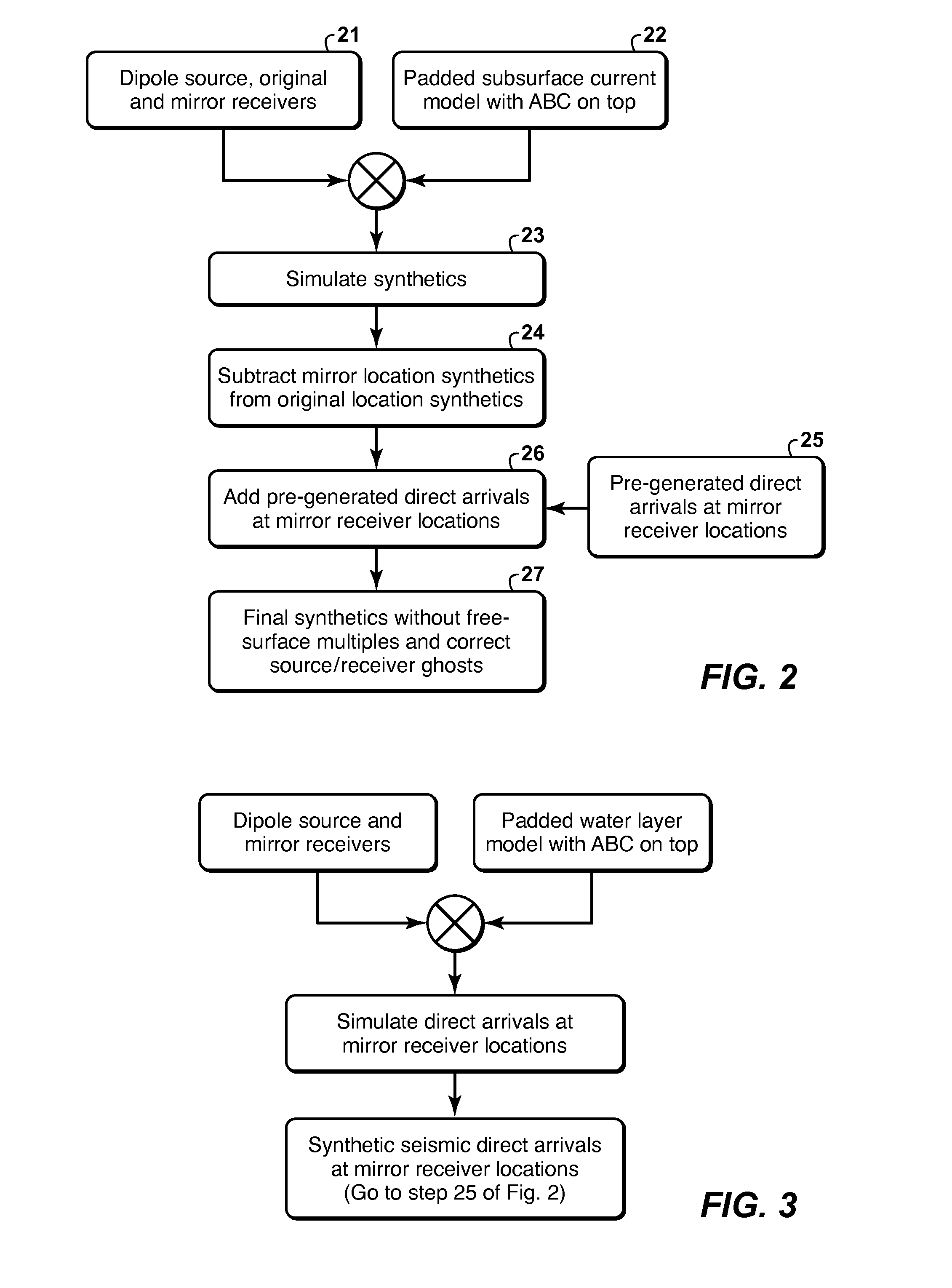
[0014]The present inventive method allows the user to accurately model and invert the direct arrivals without generating free-surface multiples in the simulated data. (Direct arrivals are seismic waves that propagate from a source directly to a receiver without reflecting from a region interface or bending.) The method also generates correct source and receiver ghosts without generating free-surface multiples.

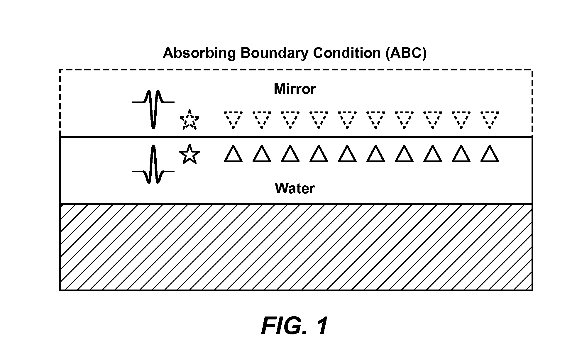
[0015]The method introduces appropriate source and receiver ghosts without modeling free-surface multiples in the simulated data. In seismic simulation, the monopole source is replaced with a dipole source which is created by including a source signature of the opposite polarity at the mirror (reflected through the plane of the free surface) location of the original source location. Other than polarity, the source signature at a mirror location is the same as the source signature at the corresponding original location. Likewise, monopole receivers are replaced with a dipole rec...


PUM


Abstract

Method for performing a full wavefield inversion (FWI) without simulating free-surface multiple reflections. The free-surface multiples are removed from the field gathers of seismic data, which are then used to generate a subsurface velocity model by FWI. In the FWI, the field monopole sources and receivers are replaced with dipole (actual and mirror image) sources and receivers (21) when model-simulating (23) synthetic survey data. Also, direct arrivals at the mirror receiver locations are preferably simulated (25) with the dipole sources for each shot location and added (26) to the synthetic survey data (24) for that shot location, resulting in corrected synthetic survey data (27), which is used in the FWI to generate residuals. A model update may be computed by back-propagating the residuals by injecting them at both mirror and actual receiver locations.

Description

CROSS-REFERENCE TO RELATED APPLICATION[0001]This application claims the benefit of U.S. Provisional Patent Application 62 / 044,728, filed Sep. 2, 2014, entitled FULL-WAVEFIELD INVERSION USING MIRROR SOURCE-RECEIVER GEOMETRY, the entirety of which is incorporated by reference herein.FIELD OF THE INVENTION[0002]The invention relates generally to the field of geophysical prospecting for hydrocarbons, and more particularly to geophysical data processing. Specifically, the invention is a method to invert seismic data containing source and receiver ghosts but no free-surface multiples.BACKGROUND OF THE INVENTION[0003]Full wavefield inversion (FWI) is a geophysical method that is used invert seismic data to infer a subsurface model of a physical property, such as velocity, that affects propagation of seismic waves through a medium. FWI is known to estimate the subsurface properties more accurately than other inversion methods such as AVO inversion. The crux of any FWI computer algorithm can...

Claims


Application Information

Patent Timeline
Patent Type & Authority Applications(United States)
IPC IPC(8): G06F17/10G01V1/28
CPCG01V1/282G06F17/10G01V2210/679G01V2210/74G01V2210/43G01V1/303G01V2210/6222G01V2210/675G01V2210/614G01V2210/56
Inventor BANSAL, REESHIDEVBAUMSTEIN, ANATOLYVDOVINA, TETYANAWANG, DONGXINGSUN, HONGCHUAN
Owner BANSAL REESHIDEV
Learn More