Multi-phase common mode choke

a common mode choke and multi-phase technology, applied in the direction of fixed inductances, power conversion systems, inductances, etc., can solve the problems of undetectable differential mode inductance between different phases, ferrite ring cores are generally no longer suitable cores for common mode chokes,

Active Publication Date: 2016-02-25
GENERAL ELECTRIC CO
View PDF5 Cites 4 Cited by
  • Summary
  • Abstract
  • Description
  • Claims
  • Application Information

AI Technical Summary

Problems solved by technology

Ferrite ring cores are generally no longer a suitable core for common mode chokes as transmission power levels continue to increase.
The absence of such spec...

Method used


Image

  • Multi-phase common mode choke
  • Multi-phase common mode choke
  • Multi-phase common mode choke

Examples


Embodiment Construction

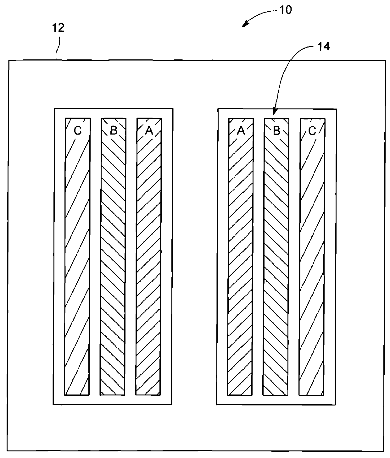
[0021]FIG. 1 is a plan view illustrating a three-phase common mode (CM) choke 10 winding arrangement on a magnetic E core 12, and that is known in the art. The three-phase CM choke 10 has a single three-phase winding group 14 arranged concentrically on the magnetic E core 12. The three-phase CM choke 10 winding arrangement presents challenges due to excessive unbalanced differential mode inductance between different phases when used as a common mode filter in medium voltage (MV) large power rating drives.

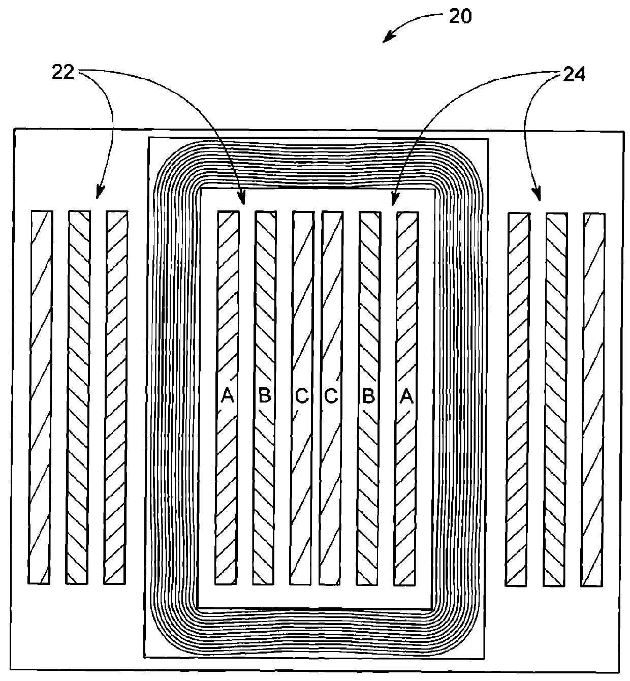
[0022]FIG. 2 is a plan view illustrating another three-phase common mode choke 20 winding arrangement that is known in the art. The three-phase CM choke 20 has a pair of three-phase winding groups 22, 24. Winding group 22 is symmetric with winding group 24. Although the winding arrangement associated with three-phase CM choke 20 results in a reduction in unbalanced differential mode inductance between different phases, this reduction may not be sufficient for use as a common mode fi...


PUM


Abstract

A common mode choke includes at least two groups of multi-phase coils wound on a magnetic core for balancing differential mode inductance between the phases. The multi-phase coils in each group are series connected and concentrically wound on a respective portion of the magnetic core. Each group of multi-phase coils is non-overlapping with each other group of multi-phase coils.

Description

BACKGROUND[0001]The subject matter of this disclosure relates generally to common mode chokes, and more particularly, to a three-phase common mode choke structure suitable for use in high power applications.[0002]Three-phase common mode chokes may be used as a common mode filter in medium voltage (MV) large power rating drives. Such common mode chokes may be a key component for an MV drive without a transformer.[0003]Ferrite ring cores are generally no longer a suitable core for common mode chokes as transmission power levels continue to increase. These increasing transmission power levels may influence the use of core and winding materials, and may necessitate the use of core and winding materials more suitable for high power magnetic devices.[0004]Further, a special winding arrangement may be required for a multi-phase choke such as a three-phase common mode choke when used at certain high transmission power levels. The absence of such special winding arrangements may otherwise ca...

Claims


Application Information

Patent Timeline
IPC IPC(8): H01F27/28H01F30/12
CPCH01F30/12H01F27/28H01F37/00H02M1/126H02M1/123
Inventor YUAN, ZHIHUIDONG, XIAOTINGSHEN, JIESCHROEDER, STEFANWEEBER, KONRAD ROMAN
Owner GENERAL ELECTRIC CO
Why Eureka
Try Eureka