Slit lamp microscope

a microscope and lamp technology, applied in the field of slit lamp microscopes, can solve the problems of difficult linkage between the control of slit light irradiation and the control of background illumination light, and the difficulty of slit light irradiation and background illumination light irradiation

Active Publication Date: 2016-02-25
KK TOPCON
View PDF3 Cites 3 Cited by
  • Summary
  • Abstract
  • Description
  • Claims
  • Application Information

AI Technical Summary

Benefits of technology

[0020]According to the present invention, it is possible to link control of

Problems solved by technology

Therefore, it is difficult to control irradiation of slit light and irradiation of background illumination light independently from each o

Method used


Image

  • Slit lamp microscope
  • Slit lamp microscope
  • Slit lamp microscope

Examples


Embodiment Construction

[0030]Examples of embodiments of slit lamp microscopes related to the present invention are explained in detail with reference to the diagrams. Note that contents of the documents cited in the specification may be incorporated as contents of the embodiments below.

[0031]First, directions are defined. The direction from a lens (objective lens) arranged closest to the subject side in a device optical system is a “front direction”, while the direction opposite thereto is a “rear direction”. Moreover, the horizontal direction orthogonal to the front direction is a “left-right direction”. Further, the direction orthogonal to both the front-rear direction and the left-right direction is a “vertical direction (upward-downward direction)”.

[Exterior Configuration]

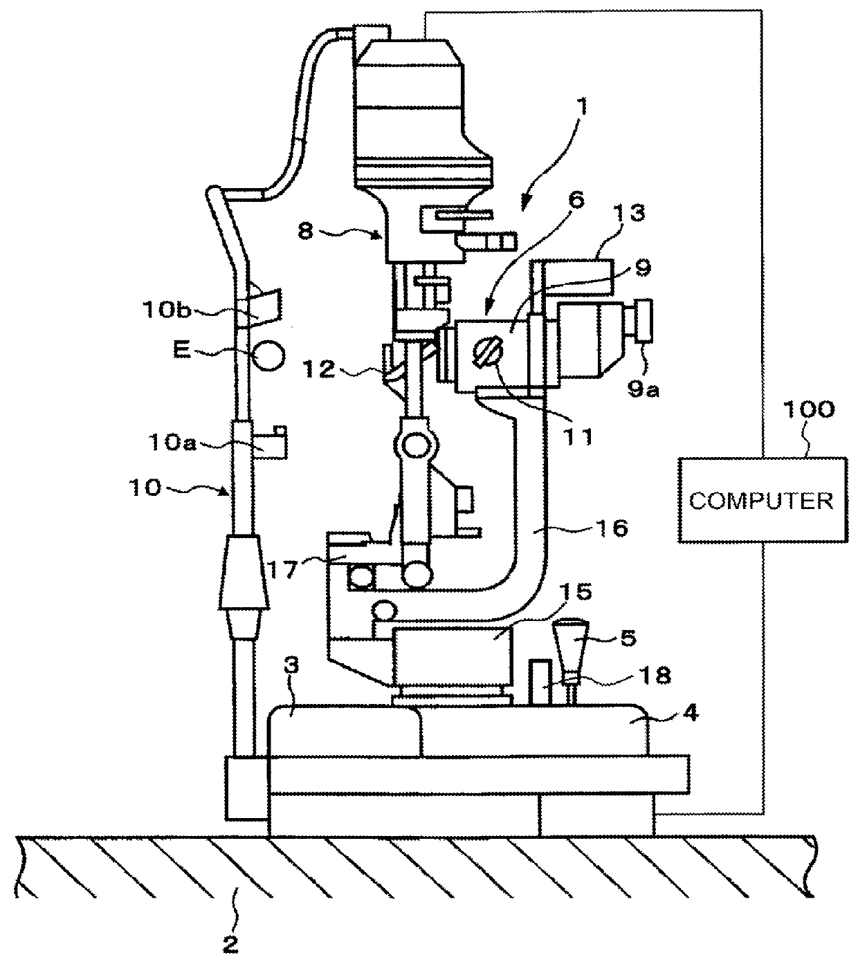
[0032]The exterior configuration of a slit lamp microscope related to the present embodiment is explained with reference to FIG. 1. A computer 100 is connected to a slit lamp microscope 1. The computer 100 performs various control pr...


PUM


Abstract

Provided is a slit lamp microscope capable of controlling irradiation of slit light and background illumination light interlockingly. Embodiment includes a main illumination system, background illumination system, observation system and controller. The main illumination system includes a first light source unit that outputs first light and slit forming unit that forms a slit with changeable width, and illuminates an eye with the first light having passed through the slit. The background illumination system includes a second light source unit that outputs second light, and illuminates a peripheral area of an eye area irradiated with the first light. The observation system includes an eyepiece lens, imaging device, and group of optical elements that guides reflected light of the first light and reflected light of the second light from the eye to the eyepiece lens and imaging device. The controller interlockingly controls the main illumination system and second light source unit.

Description

FIELD OF THE INVENTION[0001]The present invention relates to a slit lamp microscope.BACKGROUND OF THE INVENTION[0002]A slit lamp microscope is an ophthalmologic apparatus that uses slit light to cut an optical section of a cornea, thereby obtaining an image of a cross-section of the cornea. As disclosed in Patent Documents 1 and 2, a slit lamp includes a main illumination system for irradiating an eye with slit light and a background illumination system for illuminating an area around the slit light. Light irradiated to an eye by the background illumination system is referred to as background illumination light.[0003]The background illumination system is configured as an optical system that guides light output from a light source in the main illumination system. Therefore, it is difficult to control irradiation of slit light and irradiation of background illumination light independently from each other, and also difficult to link the control of irradiation of slit light with the con...

Claims


Application Information

Patent Timeline
IPC IPC(8): A61B3/135A61B3/00
CPCA61B3/0075A61B3/135
Inventor SATO, TOSHIAKITAKEDA, TAKANORIWATANABE, TAKAHIRO
Owner KK TOPCON
Why Eureka
Try Eureka