
Robust lidar sensor for broad weather, shock and vibration conditions

a lidar sensor and broad weather technology, applied in the direction of instruments, distance measurement, surveying and navigation, etc., can solve the problems of sensor module being the target of vandalism, tampering and theft, performance and durability of mechanically spinning lidar sensors are often adversely affected,

Inactive Publication Date: 2016-02-18
QUANERGY SYST
View PDF7 Cites 168 Cited by
  • Summary
  • Abstract
  • Description
  • Claims
  • Application Information

AI Technical Summary

Benefits of technology

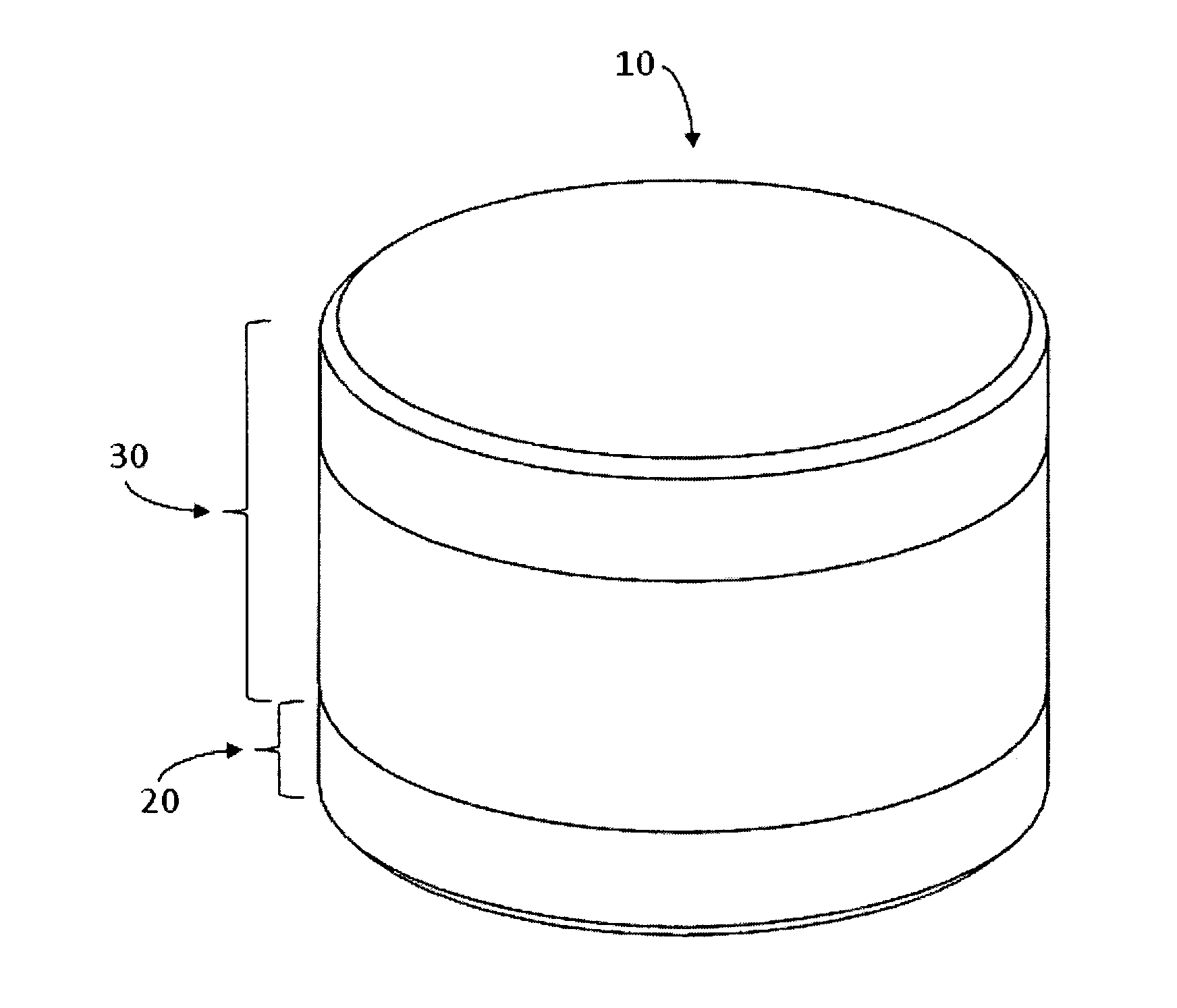
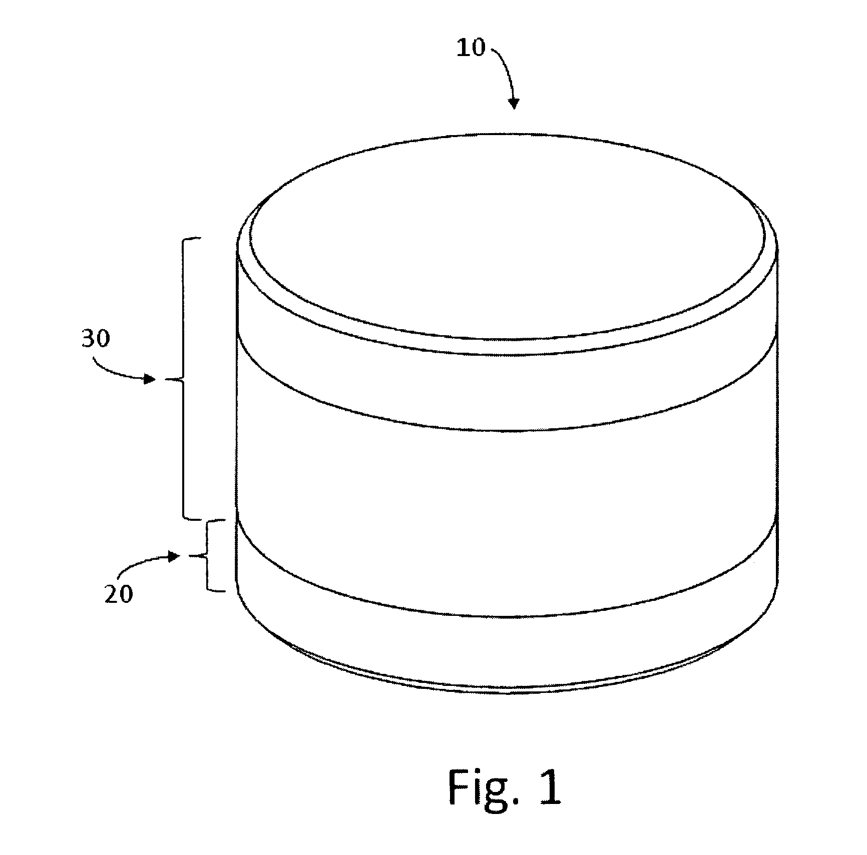
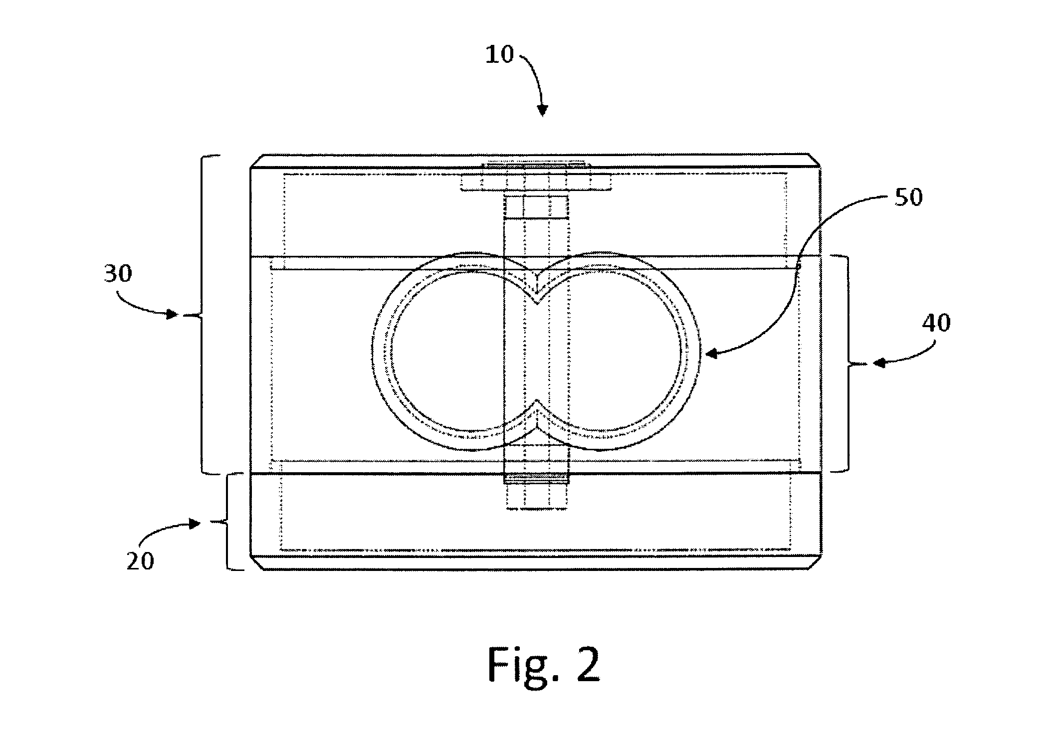
The patent describes an apparatus and method for real-time wide-field-of-view ranging with a time-of-flight lidar sensor. The invention is designed to have no moving external parts, use wireless energy and data transfer between static and spinning parts of the lidar, and have a protective body, sealant, and / or damage-resistant tamper-resistant cage. The invention can have copackaged laser emitters and / or photodetectors, and can have a single laser emitter and / or a single photodetector. The spinning speed of the lidar can be lower than 200 RPM. The head assembly is static as opposed to rotating, and only the internal turret is spinning. These technical features make the invention more efficient, reliable, and safe for various applications.

Problems solved by technology

The performance and durability of mechanically spinning lidar sensors are often adversely affected by challenging weather, shock and vibration conditions.
Moreover, the lifetime of a lidar sensor can be adversely affected by mechanical impact of solid objects (e.g., hail, rocks) and the sensor module can be the target of vandalism, tampering and theft.

Method used


Image

  • Robust lidar sensor for broad weather, shock and vibration conditions
  • Robust lidar sensor for broad weather, shock and vibration conditions
  • Robust lidar sensor for broad weather, shock and vibration conditions

Examples


Embodiment Construction

[0016]An apparatus and method are used for real-time wide-field-of-view ranging with a time-of-flight lidar sensor having one or a plurality of laser emitters and one or a plurality of photodetectors. When a plurarity of laser emitters are used, they are preferably copackaged or are in the form of an integrated multi-emitter chip in a single package or emitting multi-chip module, and when a plurarity of photodetectors are used, they are preferably copackaged or are in the form of an integrated multi-photodetector chip in a single package or photodetecting multi-chip module. Furthermore, the apparatus comprises any combination of (a) no moving external parts in contact with the environment, (b) wireless energy and data transfer between the static and the moving parts of the lidar, and (c) protective body, sealant and / or damage-resistant tamper-resistant theft-resistant cage. The preferred application is vehicle safety and efficiency.

[0017]Some of the advantages of having no moving ex...


PUM


Abstract

An apparatus and method are used for real-time wide-field-of-view ranging with a time-of-flight lidar sensor having one or a plurality of laser emitters and one or a plurality of photodetectors. When a plurarity of laser emitters are used, they are preferably copackaged or are in the form of an integrated multi-emitter chip or emitting multi-chip module in a single package, and when a plurarity of photoreceivers are used, they are preferably copackaged or are in the form of an integrated multi-photoreceiver chip or photoreceiving multi-chip module in a single package. Furthermore, the apparatus comprises any combination of (a) no moving external parts in contact with the environment, (b) wireless energy and data transfer between the static and the moving parts of the lidar, and (c) protective body, sealant and / or damage-resistant tamper-resistant theft-resistant cage.

Description

PRIORITY CLAIM[0001]The present Application claims the benefit of priority from U.S. Provisional Application Ser. No. 61 / 745,795, filed Dec. 25, 2012.REFERENCE CITED[0002]U.S. Patent Documents5,455,669October 1995Wetteborn7,746,449 B2June 2010Ray7,969,558 B2June 2011Hall2011 / 0216304 A1September 2011HallFIELD OF THE INVENTION[0003]The present invention relates generally to the field of vehicle or robot or automated equipment station safety and efficiency, and more particularly to the use of robust time-of-flight lidar sensors for real-time wide-field-of-view detection of objects surrounding a vehicle under a broad range of weather, shock and vibration conditions.BACKGROUND OF THE INVENTION[0004]A lidar sensor is a light detection and ranging sensor. It is an optical remote sensing module that can measure the distance to a target or objects in a landscape, by irradiating the target or landscape with light, using pulses from a laser, and measuring the time it takes photons to travel to...

Claims


Application Information

Patent Timeline
Patent Type & Authority Applications(United States)
IPC IPC(8): G01S17/95G01S7/481
CPCG01S17/95G01S7/4813G01S7/4815G01S7/4817G01S17/931
Inventor PACALA, ANGUSYU, TIANYUEELDADA, LOUAY
Owner QUANERGY SYST
Learn More