
Door lock device for refrigerator and freezer

a door lock and refrigerator technology, applied in the field of door lock devices, can solve the problems of reducing the productivity of the product, reducing the elastic force of the spring supporting the locking plate, and difficult to maintain the state, so as to improve the coupling structure of the inner case, facilitate the assembling and installation process, and facilitate the effect of exchanging parts

Active Publication Date: 2016-02-18
KONGJIN
View PDF0 Cites 1 Cited by
  • Summary
  • Abstract
  • Description
  • Claims
  • Application Information

AI Technical Summary

Benefits of technology

[0010]Accordingly, the present invention has been made in view of the above-mentioned problems occurring in the prior art, and it is an object of the present invention to provide a door lock device for a door of a refrigerator and freezer that is configured to improve the coupling structure of an inner case and an outer case and at the same time to reduce the whole volumes and the number of parts of opening and closing means and releasing means adapted to open and close the door, thus easily making them in an economical way, making it easy to perform assembling and installing processes, and making it simple to perform exchanging of parts and maintenance work.
[0011]It is another object of the present invention to provide a door lock device for a door of a refrigerator and freezer that is configured wherein fixing protrusions protrude from both side surfaces of an inner case fixed by means of bolts to the surface of the door in such a manner as to be press-fitted to fixing grooves formed on the inside of the front portion of an outer case and a locking protrusion formed on the inside of the rear portion of the outer case is rigidly fixed to a locking groove of the inner case, thus preventing the inner case from being exposed to the outside and making it impossible to disassemble the inner case to the outside.
[0012]It is yet another object of the present invention to provide a door lock device for a door of a refrigerator and freezer that is configured to minimize operating relations wherein a fixing portion of a locking plate fixed to a latch as opening and closing means is fixed to and escaped from a locking groove of a rotary cam, thus allowing the latch to be rapidly open, and to have guide plates disposed at the inside of the inner case, thus preventing the locking plate from being distorted upon the movement of the latch.
[0013]It is still another object of the present invention to provide a door lock device for a door of a refrigerator and freezer that is configured to have a transparent window coupled to the top plate of an outer case and key locking and releasing display means mounted under the transparent window, so that if a latch is released, a color of a releasing display portion is exposed to the outside through the transparent window, and if the latch is locked, a color of a locking display portion is exposed to the outside through the transparent window, thus making it easy to recognize the colors by the naked eyes of a user and checking the locking states of an outer handle and the latch.

Problems solved by technology

Under the above-mentioned configuration, the conventional door lock device becomes complicated in the whole coupling structures and has the difficulties in the assembling and disassembling processes, thus making the productivity of the product lowered.
According to the conventional door lock device, the guide member and the operating lever coupled to the outer handle and the operating plate coupled to the latch become complicated in configurations and have many difficulties in assembling process, and further, it is hard to maintain the state where a locking piece of the locking plate is rigidly fixed to a locking protrusion of the latch.
Besides, the elastic force of the spring supporting the locking plate may be reduced or the spring may be escaped from its original position, thus failing to release the locking state of the latch.
Accordingly, the conventional door lock device has many difficulties in the whole assembling processes and the maintenance process, thus undesirably increasing the product cost and the maintenance cost.

Method used


Image

  • Door lock device for refrigerator and freezer
  • Door lock device for refrigerator and freezer
  • Door lock device for refrigerator and freezer

Examples


Embodiment Construction

[0026]Hereinafter, an explanation on a door lock device for a door of a refrigerator and freezer according to the present invention will be in detail given with reference to the attached drawing.

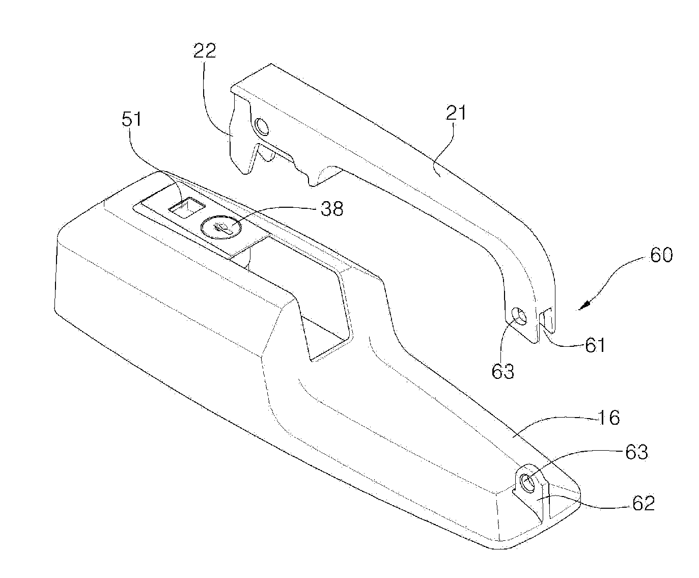
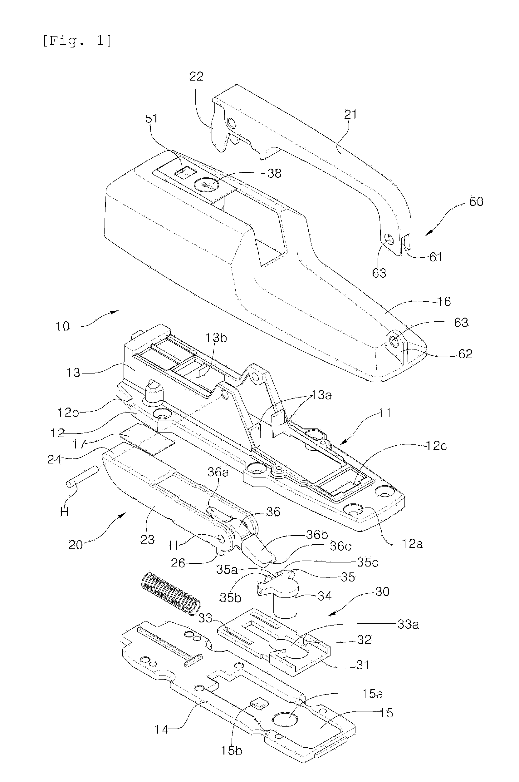
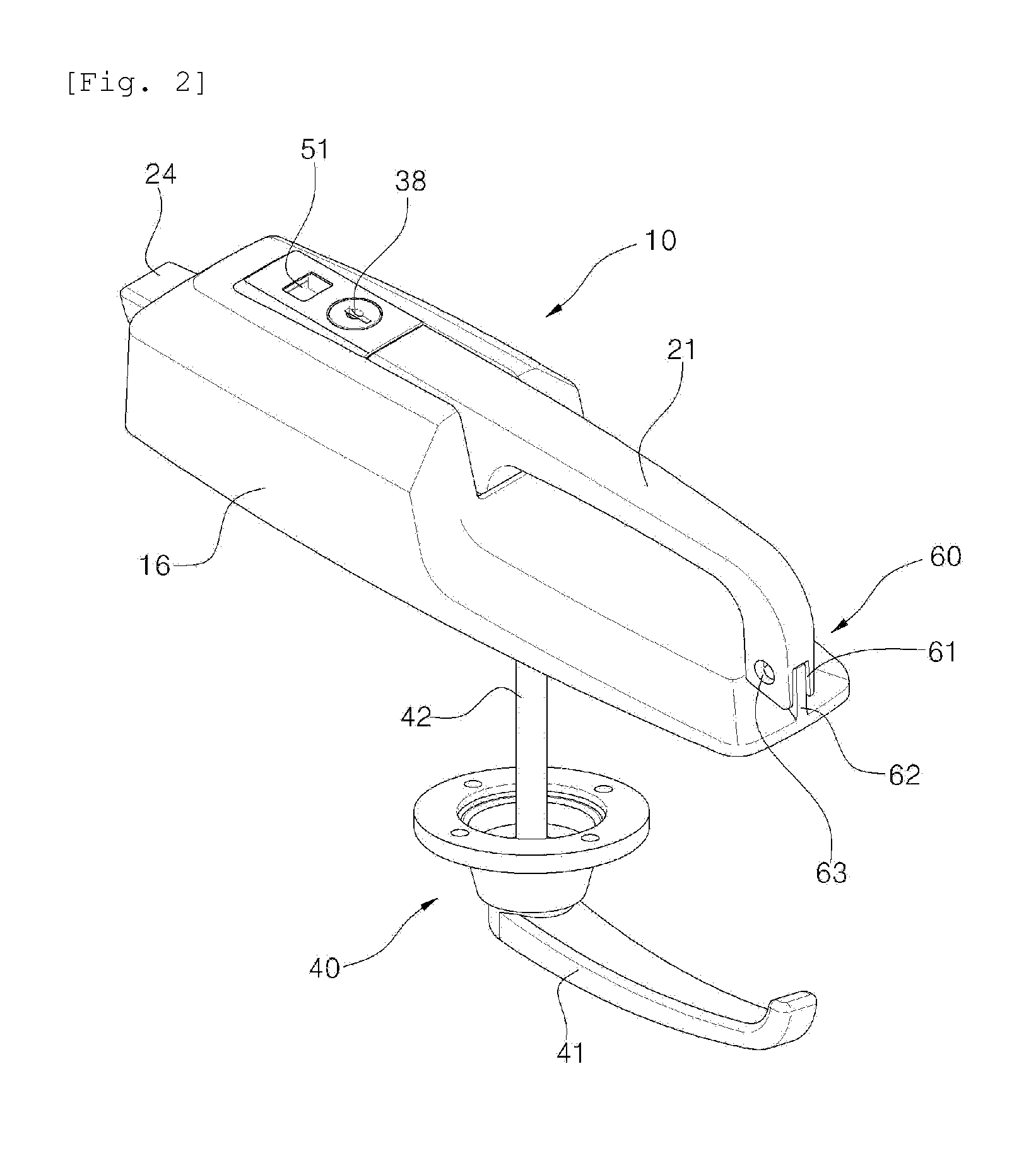
[0027]Referring to FIGS. 1 to 9, a door lock device for a door of a refrigerator and freezer according to the present invention includes: a case 10 having an inner case 11 fixed to the surface of the door and having a base plate 14 coupled to the underside thereof and an outer case 16 coupled to the external surface of the inner case 11; opening and closing means 20 adapted to move a latch 23 forward and backward by means of the operation of an outside handle 21 coupled to the inner case 11 to open and close the door; locking means 30 adapted to convert the latch 23 into a locking state in such a manner as to allow a fixing portion 36b of a locking plate 36 disposed at the rear portion of the latch 23 to be brought into close contact with a locking groove 35a formed on a rotary cam 34 dispos...


PUM


Abstract

The present invention relates to a door lock device for a door of a refrigerator and freezer, and more particularly, to a door lock device for a door of a refrigerator and freezer that is configured to improve the coupling structure of an outer case and an inner case, thus preventing the inner case fixed by means of bolts to the surface of the door from being disassembled to the outside, and to reduce the whole volumes and the number of parts of opening and closing means and releasing means adapted to open and close the door, thus making it easy to perform assembling and installing processes.

Description

BACKGROUND OF THE INVENTION [0001]1. Field of the Invention[0002]The present invention relates to a door lock device for a door of a refrigerator and freezer, and more particularly, to a door lock device for a door of a refrigerator and freezer that is configured to improve the coupling structure of an outer case and an inner case, thus preventing the inner case fixed by means of bolts to the surface of the door from being disassembled to the outside, and to reduce the whole volumes and the number of parts of opening and closing means and releasing means adapted to open and close the door, thus making it easy to perform assembling and installing processes.[0003]2. Background of the Related Art[0004]Generally, a refrigerator and freezer is used to keep articles to be cooled and frozen therein temporarily or for a long period of time, thus preventing them from being decayed, and on the other hand, a door lock device is mounted on a panel of a door.[0005]So as to mount the door lock de...

Claims


Application Information

Patent Timeline
Patent Type & Authority Applications(United States)
IPC IPC(8): E05B65/00E05B33/00E05B41/00E05C1/10
CPCE05B65/005E05C1/10E05B41/00E05B33/00E05B13/002E05B67/383E05C1/14F25D23/028Y10S292/71F25D23/02E05B15/00E05B13/10E05B65/0053E05C1/12
Inventor YUN, KYU, JUNG
Owner KONGJIN
Learn More