Structural support spacer

a technology of structural support and spacer, which is applied in the direction of girders, joists, shores, etc., can solve the problems of less than safe intermediate placement, tedious progress, and safety hazards for workers, and achieve the effect of adding rigidity or suppor

Active Publication Date: 2016-02-18
FULLER KEVIN S
View PDF0 Cites 1 Cited by
  • Summary
  • Abstract
  • Description
  • Claims
  • Application Information

AI Technical Summary

Benefits of technology

The invention provides a truss spacer that allows for easier attachment and correction of trusses in a truss manufacturing facility or at the job site. The spacer has graded indicators to show if the first end of the spacer is correctly positioned and how much correction is needed on the adjacent truss. The spacer can be easily aligned with the adjacent truss using the graded indicators on the second swing end portion. The elongate spacer has an L- or V-shaped cross-section and can be efficiently fabricated and attached to trusses. The spacer has an orthogonal or oblique angled face to provide additional rigidity or support to the combined structures. The temporary attachment means allows the spacer to be positioned flush against the upwardly facing surface of the structural support member before being activated to secure the spacer in place.

Problems solved by technology

Accurate placement of structural support members such as beams, joists, rafters, and particularly roof trusses can require several manual steps (e.g., measuring, positioning, re-measuring, temporarily tacking or bracing the members, etc.) that can result in tedious progress and less than safe intermediate placement as the framing members are erected into a building.
The brace thus has a first transport and handling position and then rotates to a second use position; however, the '378 brace does not lay flush against the surface of the structural support member when in the first transport and handling position, rather it extends upwardly exposing metal corners presenting a safety hazard to workers and subjecting the brace to damage by contact with other things during handling, storage, or transport.
Moreover, the brace does not have additional means for retaining the brace in the first transport and handling position and may swing loose during handling, such as hoisting the structural support member into position in the framing.
This can create safety issues and additional assembly problems, particularly if the brace is damaged.
Moreover, compensation means are not provided by the '378 brace for when the first pivotal connection is not accurately fastened to the structural support member.
Moreover, in that each end of the '378 brace extends entirely over both structural support members that it spans between, uniform positioning of the brace on adjacent structural support members is not possible in that the brace ends would overlap.
Thus, staggering and offsetting the braces when applied to the structural support members is required.

Method used


Image

  • Structural support spacer
  • Structural support spacer
  • Structural support spacer

Examples


Embodiment Construction

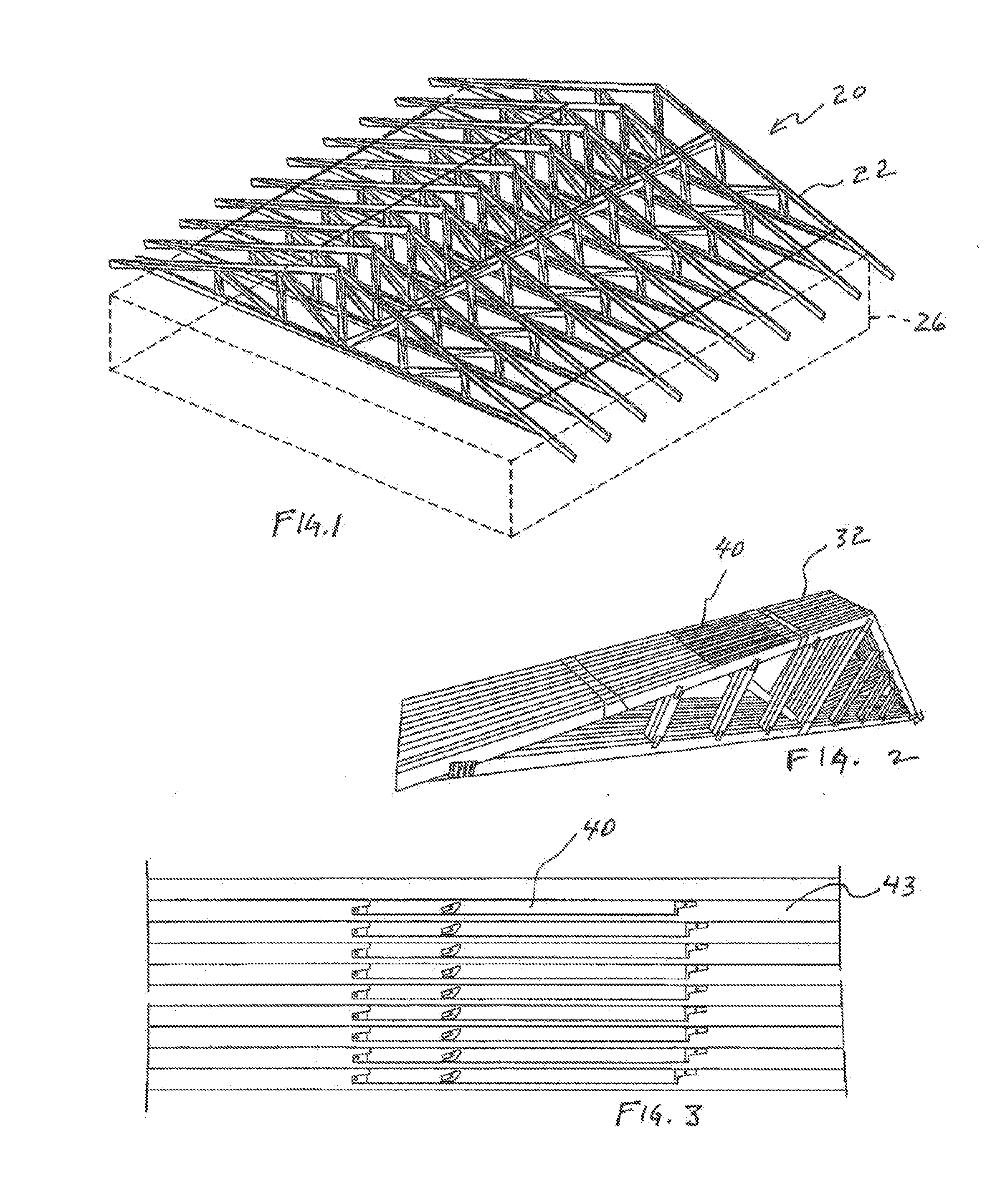
[0048]Referring to FIG. 1, the framing of a wood frame building 20 is illustrated. Structural support members 22, configured as planar roof trusses rest on a building wall structure 26 shown in dashed lines. FIG. 2 illustrates a stack 32 of such roof trusses bound together as they would be shipped to the job site from a truss manufacturing facility. The trusses of the wood frame building have spacers 40 in place for maintaining the spacing between the trusses during erection of the building. The spacers 40 are illustrated on the trusses in the stack of trusses in a transport and handling position, laying flush against an upwardly facing surface 42 of the trusses. FIG. 1 illustrates most of the spacers in a use position extending at or about 90 degrees from the planar trusses.

[0049]FIGS. 4-13 provides several detailed views of an exemplary structural support member spacer 40 according to certain embodiments. The spacer may conveniently be formed from sheet metal; other materials such...


PUM


Abstract

This disclosure relates to building trades where precise spacing between structural members ensures support via use of a plurality of elongate spacers. The spacers include at least one intermediate transit tacking member and a pair of nail- or screw-receiving apertures on opposing ends of thereof. One of the opposing ends serves as a pivoting end and the opposite end includes one or more relatively shorter member near the aperture formed therein. These member(s) can be driven into an adjacent trust or other support member while a final precise position is determined. To determine the final precise position to affix a given spacer one or more indicia is provided. Such indicia can include end edges, one or more cut-out features and / or one or more cut-out features and / or numbered or lettered (or other symbols) indicating the relative spacing from one end of the elongate spacer to the other.

Description

CROSS-REFERENCE TO RELATED APPLICATIONS[0001]The present application is a continucation of U.S. Patenet application Ser. No. 14 / 079,567, filed on Nov. 13, 2013, which claims the benefit of U.S. Provisional Application No. 61 / 725,995, filed on Nov. 13, 2012, all of which are incorporated herein in their entiretires by reference.FIELD OF THE INVENTION[0002]The invention relates to a family of alignment, spacing, and attachment methods and apparatus providing for the precise positioning of framing members in the construction of various structures such as wood framed buildings; in particular, the disclosure relates to unitary members that temporarily couple to pre-fabricated trusses or the like during transit or before final positioning the truss as part of the structure to a building site and then are easily, efficiently, and accurately uncoupled, rotated, and tacked into precise position between adjacent truss members.BACKGROUND OF THE INVENTION[0003]Accurate placement of structural s...

Claims


Application Information

Patent Timeline
Patent Type & Authority Applications(United States)
IPC IPC(8): E04B1/343E04B7/02E04C3/02
CPCE04B7/024E04C3/02E04C2003/026E04B1/34384E04B1/34315E04G21/1891E04B7/022E04G25/00
Inventor FULLER, KEVIN S.ALTENDORF, WAYDE J.WARE, STEPHEN J.BISHOP, ALLEN J.
Owner FULLER KEVIN S
Why Eureka
Try Eureka