Contact

a technology of contact and impedance, applied in the field of contact, can solve the problems of high-frequency signal reflection, sharp changes in impedance at these boundaries, etc., and achieve the effects of reducing reflection, reducing high-frequency signal reflection, and reducing the sharp change of impedance of the conta

Active Publication Date: 2016-02-11
HOSIDEN CORP
View PDF16 Cites 0 Cited by
  • Summary
  • Abstract
  • Description
  • Claims
  • Application Information

AI Technical Summary

Benefits of technology

[0015]The contact of this aspect can reduce reflection of high-frequency signals transmitted though the contact for the following reasons. The first sloped portion of the middle part slopes down toward the first end portion of the second connectable part, and the second sloped portion of the middle part slopes down toward the second end portion of the second connectable part. Accordingly, the contact gently changes in shape at the boundary between the first wall of the first connectable part and the first sloped portion of the middle part (first boundary), the boundary between the first sloped portion of the middle part and the first end portion of the second connectable part (second boundary), the boundary between the second wall of the first connectable part and the second sloped portion of the middle part (third boundary), and the boundary between the second sloped portion of the middle part and the second end portion of the second connectable part (fourth boundary). This configuration can reduce sharp changes of impedances of the contact at the first to fourth boundaries, resulting in reduced reflection of high-frequency signals.
[0016]The first sloped portion may have a slope angle of not greater than about 60 degrees relative to a first imaginary line. The first imaginary line may extend in the first direction through a boundary between the first sloped portion and the first end portion of the second connectable part. The second sloped portion may have a slope angle of not greater than about 60 degrees relative to a second imaginary line. The second imaginary line may extend in the first direction through a boundary between the second sloped portion and the second end portion of the second connectable part. The contact of this aspect can further reduce reflection of high-frequency signals for the following reasons. With the slope angle of the first sloped portion being not greater than about 60 degrees relative to the first imaginary line, the contact gently changes in shape, particularly from the first wall of the first connectable part to the first sloped portion of the middle part, and from the first sloped portion of the middle part to the first end portion of the second connectable part. With the slope angle of the second sloped portion being not greater than about 60 degrees relative to the second imaginary line, the contact gently changes in shape also from the second wall of the first connectable part to the second sloped portion of the middle part and from the second sloped portion of the middle part to the second end portion of the second connectable part. This configuration can further reduce sharp changes of impedances at the first to fourth boundaries, resulting in further reduced reflection of high-frequency signals.
[0017]The first sloped portion may have a slope angle of not greater than about 45 degrees relative to the first imaginary line. The second sloped portion may have a slope angle of not greater than about 45 degrees relative to the second imaginary line. The contact of this aspect can further reduce reflection of high-frequency signals for the following reasons. With the slope angle of the first sloped portion being not greater than about 45 degrees relative to the first imaginary line, the contact gently changes in shape, particularly from the first wall of the first connectable part to the first sloped portion of the middle part, and from the first sloped portion of the middle part to the first end portion of the second connectable part. With the slope angle of the second sloped portion being not greater than about 45 degrees relative to the second imaginary line, the contact gently changes in shape, also from the second wall of the first connectable part to the second sloped portion of the middle part, and from the second sloped portion of the middle part to the second end portion of the second connectable part. This configuration can further reduce sharp changes of impedances at the first to fourth boundaries, resulting in further reduced reflection of high-frequency signals.

Problems solved by technology

These sharp changes cause sharp changes in impedance at these boundaries.
When the conventional contact is used to transmit high-frequency signals, the above-mentioned sharp impedance changes can cause reflection of the high-frequency signals.

Method used


Image

  • Contact
  • Contact
  • Contact

Examples


first embodiment

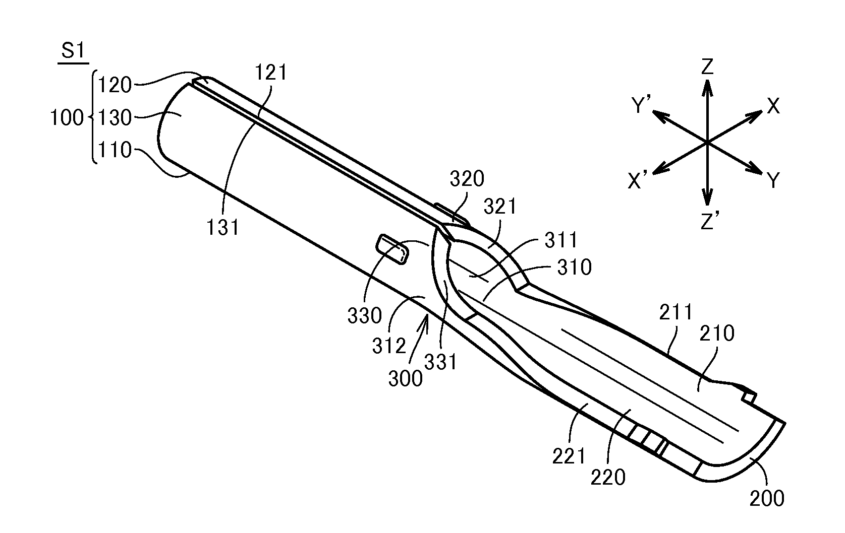
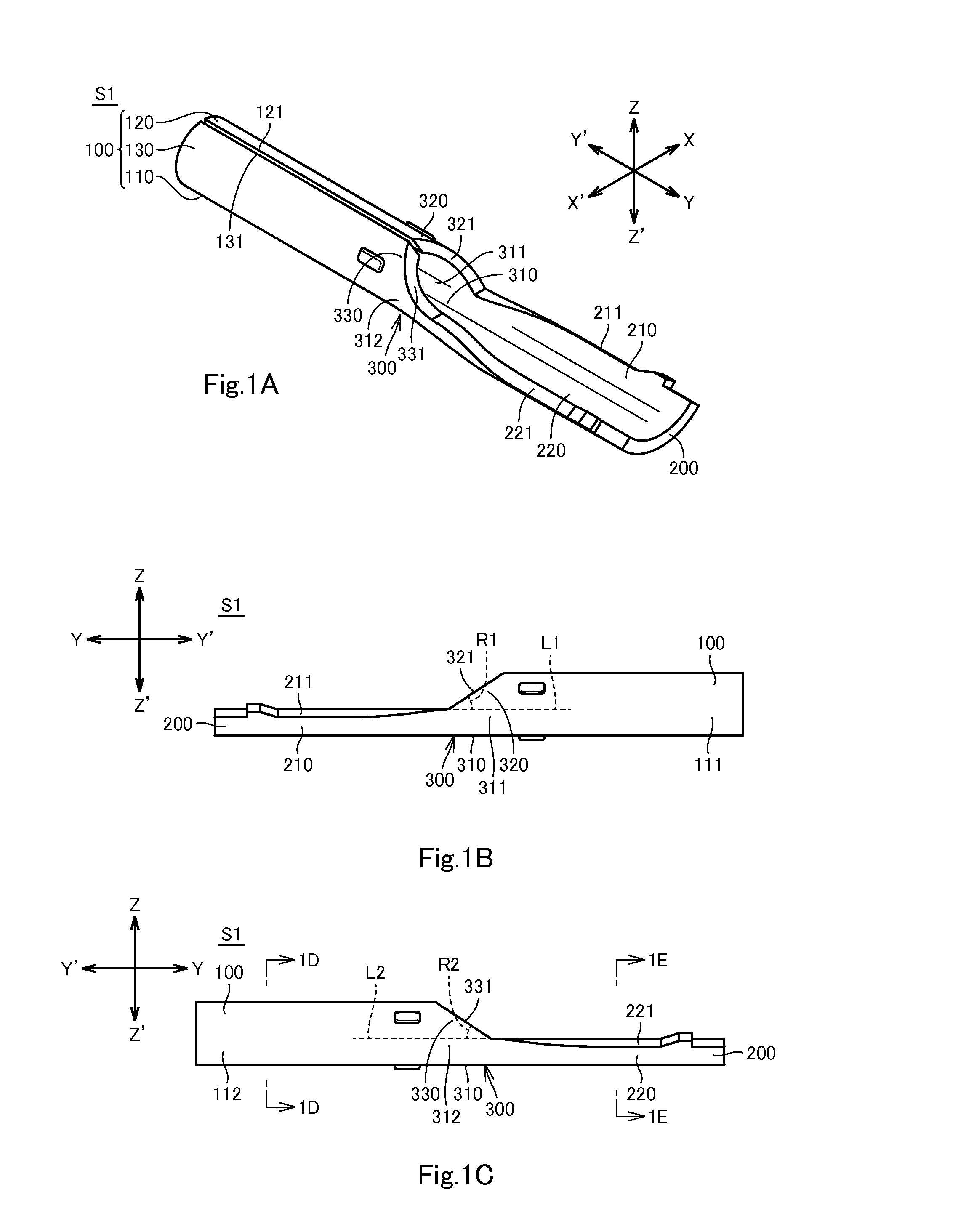
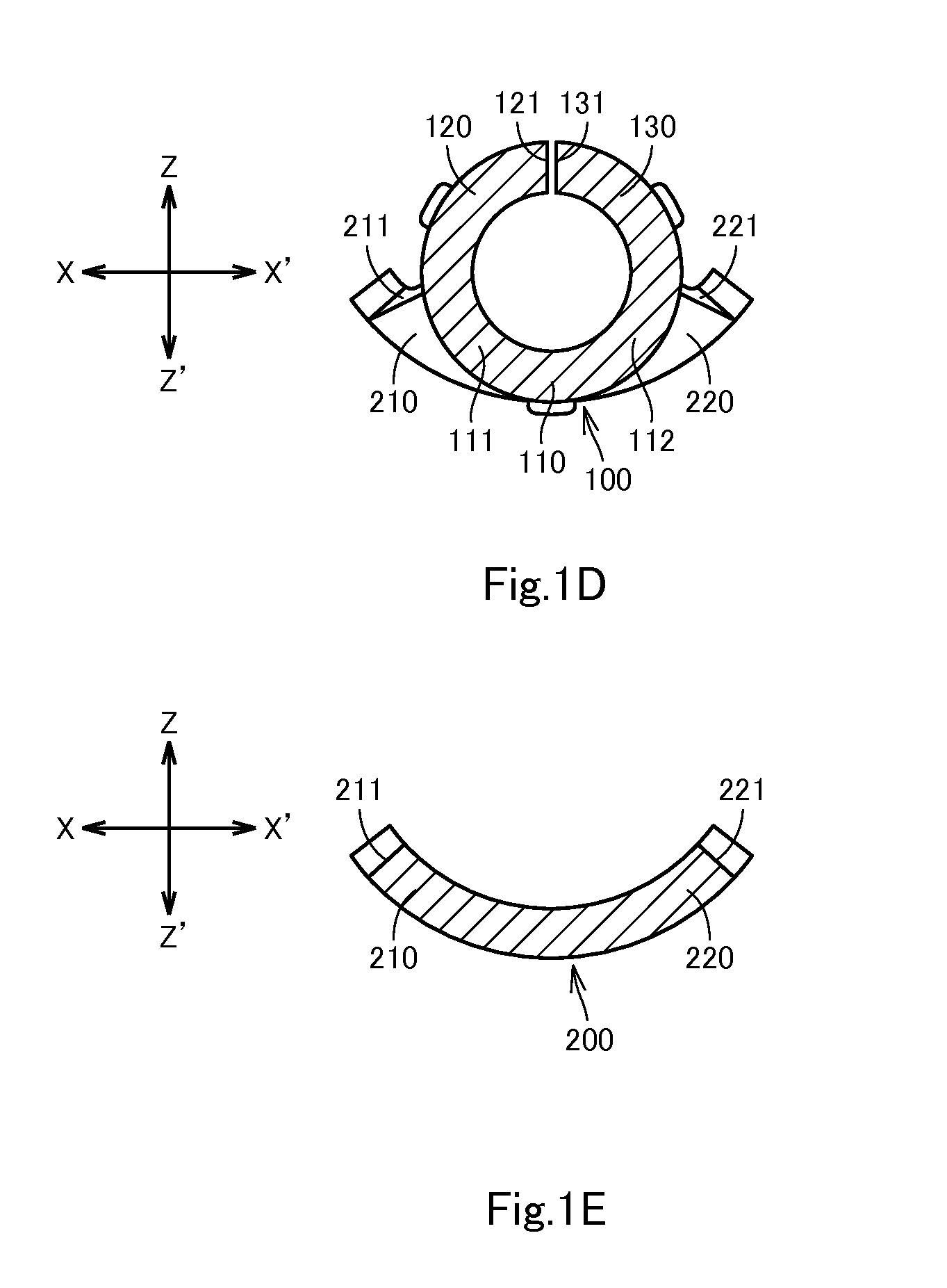
[0042]A contact S1 in accordance with the first embodiment of the invention will be described with reference to FIG. 1A to FIG. 1E. The contact S1 is formed of a metal plate having electrical conductivity. The contact S1 includes a first connectable part 100, a second connectable part 200, and a middle part 300. These components of the contact S1 will be described below in detail. It should be appreciated that the Y-Y′ direction indicated in FIG. 1A to FIG. 1C corresponds to the longitudinal direction of the contact S1 and to the “first direction” recited in the claims. Of the Y-Y′ direction, the Y direction corresponds to one side of the first direction, and the Y′ direction corresponds to the other side of the first direction. The X-X′ direction indicated in FIG. 1A, FIG. 1D and FIG. 1E corresponds to the lateral direction of the contact S1 and to the “second direction” recited in the claims. Of the X-X′ direction, the X direction corresponds to one side of the second direction, a...

second embodiment

[0061]A contact S2 in accordance with the second embodiment of the invention will be described with reference to FIG. 2A to FIG. 2C. The contact S2 is formed of a metal plate having electrical conductivity. The contact S2 has the same configuration as the contact S1, except that the contact S2 includes a first connectable part 400 of different configuration from that of the first connectable part 100 of the contact S1 of the first embodiment. The differences will be described below in detail and overlapping descriptions will be omitted. The Y-Y′ direction and the X-X′ direction are indicated in FIG. 2A to FIG. 2B, the Z-Z′ direction is indicated in FIG. 2A to FIG. 2B in a similar manner as in the first embodiment.

[0062]The first connectable part 400 includes a tube T and a pair of arms 440, 450. The tube T has substantially the same configuration as that of the first connectable part 100 of the first embodiment. As shown in FIGS. 2A to FIG. 2B, the tube T includes a base 410, a firs...

third embodiment

[0067]A contact S3 in accordance with the third embodiment of the invention will be described below with reference to FIG. 3. The contact S3 is formed of a metal plate having electrical conductivity. The contact S3 has a similar configuration as the contact S1 but includes a first connectable part 100′, a second connectable part 200′, and a middle part 300′ of different shapes from those of the first connectable part 100, the second connectable part 200, and the middle part 300, respectively, of the contact S1 in the first embodiment. The differences will be described below in detail and overlapping descriptions will be omitted. The Y-Y′ direction, the X-X′ direction, and the Z-Z′ direction are indicated in FIG. 3 in a similar manner as in the first embodiment.

[0068]The first connectable part 100′ is a rectangular tube extending in the Y-Y′ direction. The base 110′ of the first connectable part 100′ is a plate of generally angular U-shape in sectional view. The first wall 120′ of th...


PUM


Abstract

A contact including a first connectable part, a second connectable part, and a middle part. The first connectable part includes a tube or plate. The plate has a cross section generally of U-shape, V-shape, C-shape, or L-shape. The tube or the plate includes a base and a first wall. The first wall extends from a first end portion of the base. The middle part includes a base and a first sloped portion. The base of the middle part is contiguously connected between the base of the first connectable part and the second connectable part. The first sloped portion is contiguously connected between the first wall and a first end portion of the second connectable part. The first sloped portion extends from a first end portion of the base of the middle part such that the first sloped portion slopes down toward the first end portion of the second connectable part.

Description

CROSS-REFERENCE TO RELATED APPLICATIONS[0001]The present application claims priority under 35 U.S.C. §119 of Japanese Patent Application No. 2014-163006 filed on Aug. 8, 2014, the disclosure of which is expressly incorporated by reference herein in its entity.BACKGROUND OF THE INVENTION[0002]1. Technical Field[0003]The invention relates to contacts.[0004]2. Background Art[0005]Japanese Unexamined Patent Publication No. 2010-177125 describes a conventional contact. The contact is formed of a metal plate. The contact includes a first connectable part, a second connectable part, and a middle part between the first and second connectable parts. The first connectable part is a rectangular tube and connectable to a terminal of a connector etc. The second connectable part is a generally U-shaped plate with two distal ends. When the second connectable part receives a core of a cable, the front ends are crimped toward the core. The middle part is a generally U-shaped plate and has a smaller ...

Claims


Application Information

Patent Timeline
Patent Type & Authority Applications(United States)
IPC IPC(8): H01R4/16
CPCH01R4/16H01R13/111H01R13/6474
Inventor KONDO, HAYATO
Owner HOSIDEN CORP
Why Eureka
Try Eureka