Sensor calibration method, computer program and computer readable medium

a technology of computer program and sensor, applied in the field of sensor calibration method, can solve the problems of tedious latency of sensors, and achieve the effect of effectively minimizing fixed pattern nois

Inactive Publication Date: 2016-02-11
FLIR SYST AB
View PDF1 Cites 31 Cited by
  • Summary
  • Abstract
  • Description
  • Claims
  • Application Information

AI Technical Summary

Benefits of technology

[0004]The purpose of the present invention is to provide a method that corrects for gain and offset, and the difference in non-lin...

Problems solved by technology

By way of the proposed method, an effective minimization of the fixed pattern noise to near zero across the sensor's entire dynamic range is achieved, without do...

Method used


Image

  • Sensor calibration method, computer program and computer readable medium
  • Sensor calibration method, computer program and computer readable medium
  • Sensor calibration method, computer program and computer readable medium

Examples


Embodiment Construction

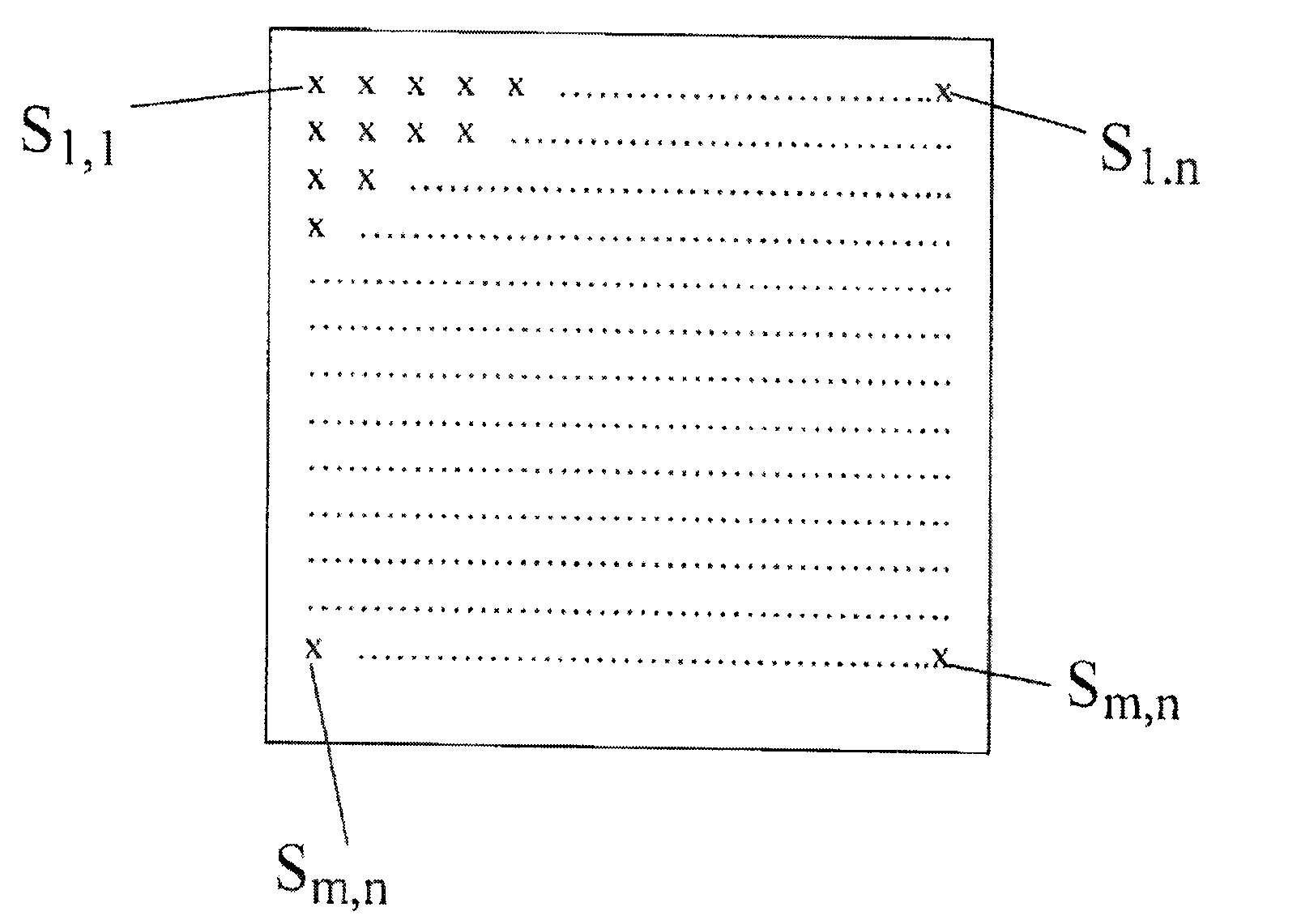
[0016]The IR sensor 1 showed in FIG. 1 comprises m x n sensor elements S1,1-Sm,n, distributed across m rows and n columns. The sensor can consist of a focal plane array, IR-FPA. Each individual sensor element S1,1-Sm,n included in the sensor 1 can have its own gain curve.

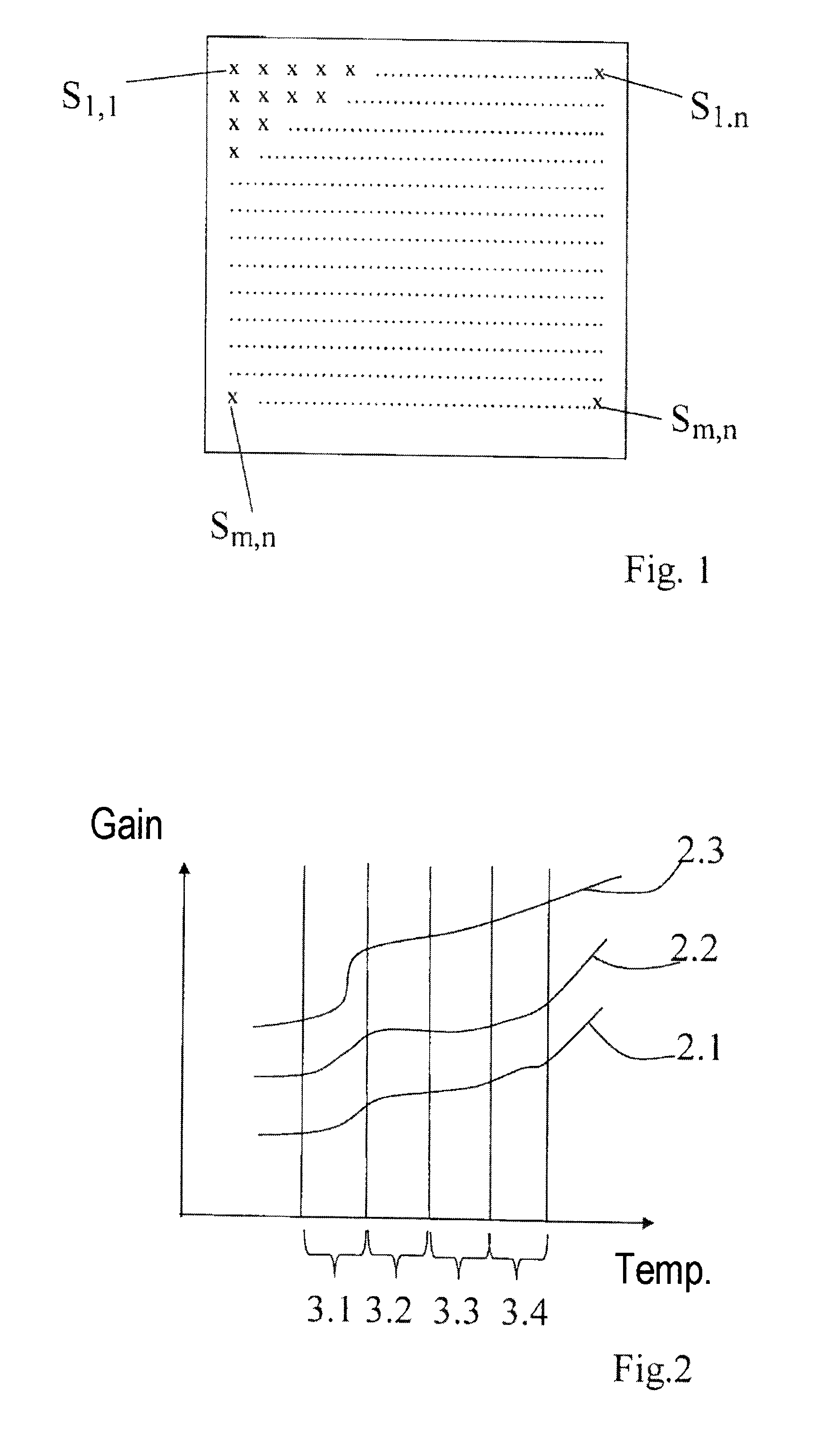
[0017]FIG. 2 shows examples of some gain curves 2.1, 2.2 and 2.3 as a function of the temperature T. As shown in the figure, the individual gain curves can exhibit very different curve shapes. Vertical lines divide the sensor's dynamic range into intervals. In FIG. 2 four ranges 3.1-3.4 have been marked. In case the sensor elements have very different shapes, an even more extensive division of the sensor's dynamic range into intervals is required than if the curve shapes of the sensors are similar.

[0018]The principles behind the invention will be explained below with reference to the schematic flowchart shown in FIG. 3.

[0019]An IR sensor included in Block 4 delivers an image to Block 5. In Block 5 the sensor's dynam...


PUM


Abstract

The invention relates to a method for the calibration of sensors of the type that comprises a plurality of sensor elements, such as focal plane arrays, FPAs, for detecting infrared radiation, IR-FPA, the calibration being performed at least two temperatures. According to the invention, the sensor's dynamic range is divided into a plurality of intervals (5), a correction map is updated on a miming basis in each interval by a scene-based non-uniformity correction (6), the correction terms between adjacent intervals are interpolated (7), and the interpolated correction terms are made to correct the sensor elements of the relevant sensor (8). The invention also relates to a computer program and a computer program product. By way of the invention, a method is provided which effectively minimizes the fixed pattern noise to near zero across the entire dynamic range of the sensor, regardless of the type of non-linearity.

Description

FIELD OF THE INVENTION[0001]The present invention relates to a method for the calibration of sensors of the type that comprises a plurality of sensor elements, such as focal plane arrays, FPAs, for detecting infrared radiation, IR-FPA, the calibration being performed at at least two temperatures. The invention also relates to a computer program comprising program code, which, when said program code is executed on a computer, causes said computer to perform the method, as well as a computer program product comprising a computer readable medium and a computer program according to the above, said computer program being comprised in said computer readable medium.BACKGROUND[0002]The output signal from the sensor elements of a sensor, such as an IR-FPA, can vary quite considerably as a function of incident power. The sensor elements therefore need to be calibrated between themselves. For example, the sensor elements included in a sensor of an IR camera do not behave the same way, but exhi...

Claims


Application Information

Patent Timeline
IPC IPC(8): G01J5/10G01J5/80H04N5/33H04N25/671H04N25/672
CPCG01J5/10G01J2005/0077G01J2005/0048H04N5/33H04N17/002G01J5/80H04N25/671H04N25/672G01J5/02
Inventor OLSSON, STEFAN
Owner FLIR SYST AB
Why Eureka
Try Eureka