
Ceramic Chute Liner

a technology of ceramic chutes and linings, which is applied in the direction of chutes, transportation and packaging, etc., can solve the problems of affecting the quality of chutes, and affecting the production efficiency of chutes, so as to achieve the effect of durable and compactness and substantial nullification of the chance of dislodging between ceramic blocks during operation

Inactive Publication Date: 2016-02-11
TEGA IND LTD
View PDF4 Cites 1 Cited by
  • Summary
  • Abstract
  • Description
  • Claims
  • Application Information

AI Technical Summary

Benefits of technology

This invention is about a ceramic chute liner that is durable, compact, and designed to prevent parts from getting stuck during operation. It also has a longer lifespan in critical conditions, a predictable wear pattern, and reduces maintenance costs. Additionally, it is easy to replace and maintain.

Problems solved by technology

Since the ore particles are dense and hard and discharged from the conveyor belt to the chute at considerable velocity, they may scratch and scrape away on the surface of the chute resulting in severe chute wear, if left unprotected.
This wear may finally tear the plate, forming holes in chute faces, leading to leakage of material.
Hence chutes have to be replaced, which activity stops the production for a long time.
This downtime while the conveyer system is not in operation, results in loss of productivity.
However, during different application, the liner is subjected not only to abrasion wear but also to a certain degree of impact wear.
It has been observed that in the conventional ceramic liners there is a tendency of ceramic blocks getting dislodged during operation.
Once a single block gets dislodged, the surrounding area becomes prone for adjacent blocks to get dislodged.
This leads ultimately to the failure of the liner.
Worn or damaged liners may periodically be removed from a chute and replaced with new liners which is disadvantageous from a maintenance point of view as the existing conventional liners are fixed with the chute by bolting the liners with the chute wall, thus making the replacement process difficult, labour intensive and time consuming.

Method used


Image

  • Ceramic Chute Liner
  • Ceramic Chute Liner
  • Ceramic Chute Liner

Examples


Embodiment Construction

[0034]The following describes exemplary preferred embodiments of the present invention, which are purely for the sake of understanding the performance of the invention, and do not impose any limitation on its scope.

[0035]All through the specification including the claims, the words “chute”, “hopper”, “conveyor”, “belt”, “liner”, “bulk material”, “abrasion”, “wear”, “impact load”, “rubber pad” and “ceramic blocks”, “protrusions”, “depressions”, “grooves”, “notches or tips” are to be interpreted in the broadest sense of the respective terms, and include all similar items in the field known by other terms, as may be clear to persons skilled in art. Restriction or limitation if any referred to in the specification, is solely by way of example and understanding the present invention.

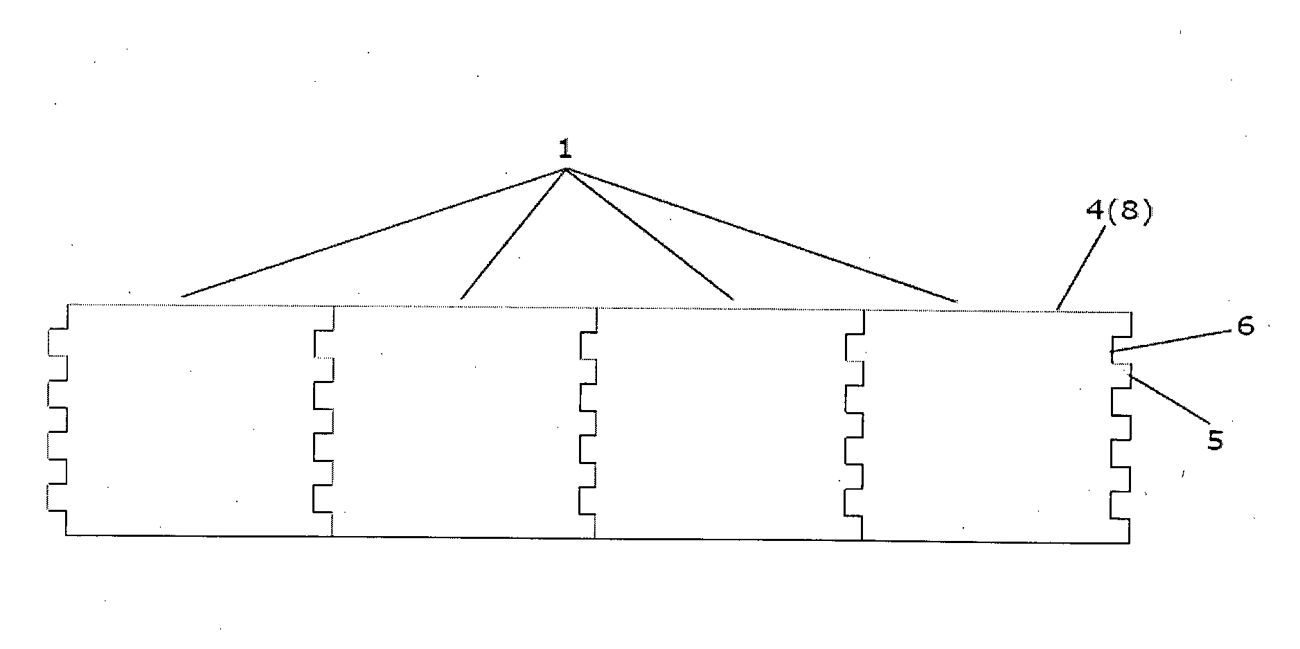
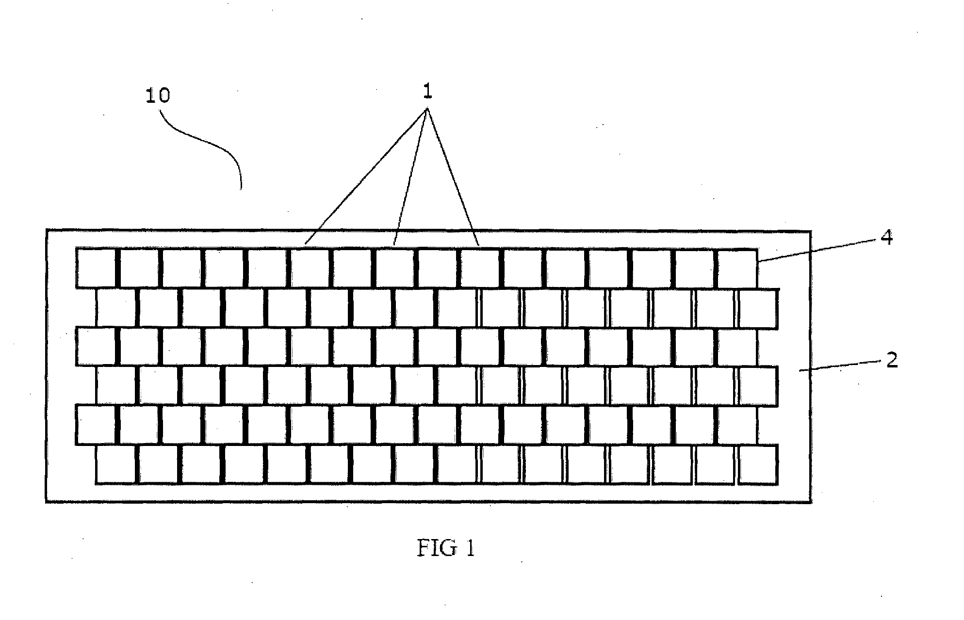
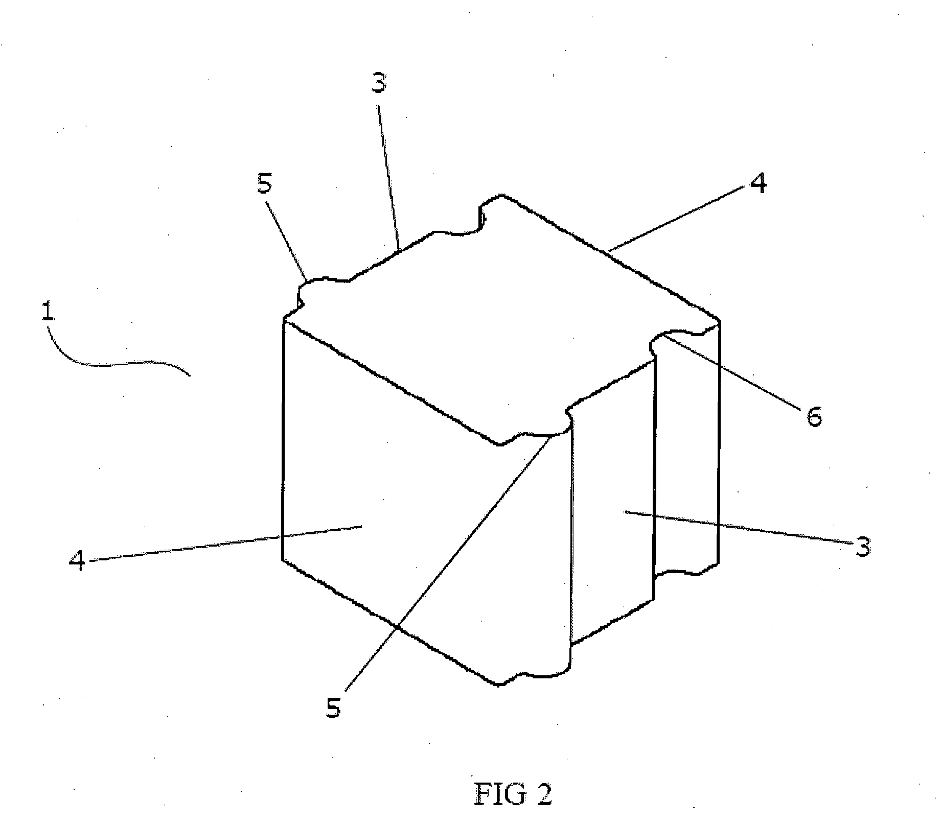
[0036]The present invention provides composite liners made up of interlocked ceramic blocks characterized in having thin rubber film between them and the blocks being embedded on a rubber matrix. Such a linin...


PUM

PropertyMeasurementUnit
strengthaaaaaaaaaa
mechanical interlockingaaaaaaaaaa
chemical bondingaaaaaaaaaa

Abstract

A ceramic chute liner (10) comprising of a plurality of mechanically interlocked ceramic blocks (1). The corresponding mechanically interlocked ceramic blocks (1) have rubber films between them along respective adjoining surfaces such that, the ceramic blocks (1) are bonded with each other with substantial strength and the impact force is substantially reduced.

Description

FIELD OF THE INVENTION[0001]The present invention relates in general to chute liners in bulk material handling, and in particular to a mechanically interlocked ceramic chute lining system where the ceramic blocks forming the liner are mechanically interlocked, the ceramic blocks are embedded on a rubber matrix for providing padding effect and include a base metal adapted for fixing the liner assembly with the chute wall by means of studs.BACKGROUND AND PRIOR ART[0002]In material handling operations, conveyor belts are used for conveying or transporting material from one station to another station. When material has to be transferred between conveyors at different heights or between conveyors moving in different directions, chutes are used. Chutes are flat plates, having relatively smooth transferring surface, arranged at different angles to transfer or guide materials along the chute under force of gravity. Since the ore particles are dense and hard and discharged from the conveyor ...

Claims


Application Information

Patent Timeline
Patent Type & Authority Applications(United States)
IPC IPC(8): B65G11/16
CPCB65G11/166
Inventor DAS, GOUR, CHANDRA
Owner TEGA IND LTD
Learn More