
Self-configuring traffic signal controller

a traffic signal and self-configuration technology, applied in the direction of road vehicle traffic control, traffic signal control, controlling traffic signals, etc., can solve the problems of signal retiming being a significant sustaining cost for most transportation agencies, and most agencies lack the resources to properly follow this process

Active Publication Date: 2016-01-28
ECONOLITE GRP
View PDF4 Cites 141 Cited by
  • Summary
  • Abstract
  • Description
  • Claims
  • Application Information

AI Technical Summary

Benefits of technology

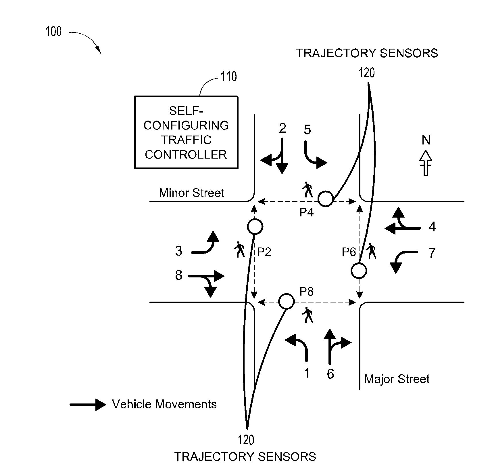
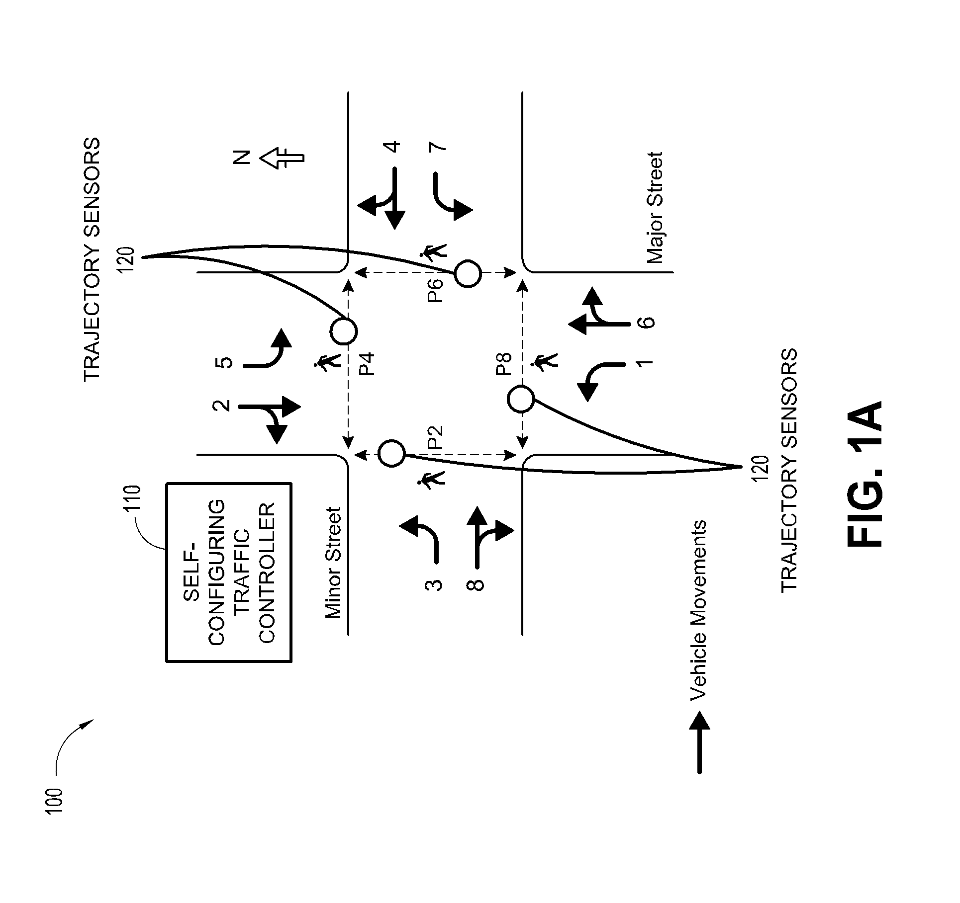
The patent describes a self-configuring traffic signal controller system that uses sensor data to adjust signal timing at intersections. The system includes trajectory sensors, such as radar or video cameras, installed at masts, wires, or poles at intersections. The sensors provide data on the position, velocity, and acceleration of vehicles approaching the intersection. The system also includes a traffic controller that uses this data to compute a delay factor, a stop factor, a capacity, an emissions factor, and a safety factor. The controller then adjusts the signal timing at the intersection based on these factors. The system can also use preconfigured geometric intersection data and user-defined weights to prioritize different factors. The system can automatically reconfigure the signal timing configuration multiple times per day based on the trajectory data. Overall, the system provides a more accurate and efficient way to control traffic signals at intersections.

Problems solved by technology

This can be a very labor-intensive process that traffic engineers should follow to establish proper signal configuration.
This signal retiming can be a significant sustaining cost for most transportation agencies, with typical signal retiming costs estimated at approximately $3,000-5,000 per signal.
Most agencies lack the resources to properly follow this process.
Given the processes for signal timing can be well established, this response reveals that agencies do not have the manpower nor financial mechanism to maintain good signal timing across their jurisdictions.
Most agencies cannot afford the costs associated with vehicle detection on all intersection approaches.
Moreover, traffic controllers do not have information regarding the number of lanes, spatial orientation, size of the intersection or other geometric information of the intersection.
Traffic controllers do not utilize maps of the local intersection and can be limited to control these phases without regard for the intersection geometrics.
Configuration of the traffic controller can be a very manually-intensive process that may requires the traffic engineer to provide many manual data inputs and perform manual calculations.
This ad-hoc practice can be both arduous and fraught with human error.
Traffic controllers do not have awareness of these policies and thus can do little to ensure that initial configuration or future operation can be consistent with these policies.
Furthermore, the traffic controller may transcend the prior efficiency and safety limitations within the standardized mechanism of traffic control.
This process can be multi-staged, and may requires considerable human-in-the-loop computation and analysis.
This image file can be used for user interface / display purposes and may not provide information to be applied for traffic control.
Smaller agencies, however, often do not follow this level of formality and merely trust the judgment of the traffic engineer to apply appropriate practices when configuring the intersection controller.
In some embodiments, the traffic controller 210 does not provide pedestrian storage within a median, such applications may require pedestrian timing override by the traffic engineer.
Opposing left turns may have a turning radius conflict and cannot be serviced concurrently.
Left turning vehicles can erroneously assume the opposing through movement is also terminating, and may perform a permissive left turn under false assumption that the opposing vehicles can be stopping.
Due to the heightened safety risks associated with RR preemption, the traffic controller 210 may not automatically implement RR preemptors on a policy basis.
However, the ITE equation for yellow clearance does not provide sufficient yellow clearance time for low and high speed approaches, and can be increased by the traffic controller 210 to allow full passage of vehicles within the dilemma zone.
A similar example holds for very slow speed approaches were the yellow clearance may not be sufficient for restrictive yellow passage through the intersection.
Moreover, this infrastructure may requires significant ongoing maintenance to keep its detection systems operational.
However, such a prerequisite would not be grounded in the financial and maintenance constraints that most agencies operate under.
Oftentimes, multiple lanes can be spanned with a single detection zone, leading to ambiguity regarding the number of vehicles awaiting service across those lanes spanned by the detectors.
Oftentimes, multiple lanes can be spanned with a single detection zone, leading to ambiguity regarding the number of vehicles or lanes awaiting service.
Oftentimes, multiple lanes can be spanned with a single detection zone, leading to ambiguity of the lane that the vehicle was detected within.
These tracking-based detection systems do not provide perfect measurement of vehicles and their trajectories.
These detection systems are not likely to have true GIS positioning of their field of view.
Even after applying translation of coordinate reference frames, there may be additional correction issues based upon the nature and quality of the detection source.
As example, Doppler-radar based sensors provide a very accurate speed measurement, but cannot provide as accurate distance ranging.
Video detection inputs, on the other hand, can have a more accurate position but may not generate accurate speed measurement.
This can be due to mid-block ingress / egress patterns onto the roadway network or errors within the early stage detection sources.
This last minute lane selection does not provide adequate prior modeling of vehicular demand for turning movement demands.
Inherent tradeoffs exist between these objectives.
As one example, the safest possible intersection can be also highly inefficient.
As another example, increases to intersection capacity also increase delays to side street movements.
Modern traffic controllers do not support control in accordance with a prioritization of these objectives.
Current detection systems are not able to accurately determine the specific vehicle type and more importantly, the fuel type (gas or diesel).
This assumption can be valid due to the nature of safety issues being near field imminent conflicts and not something that can be accurately projected far into the future.
This can also include permissively turning vehicles that can be predicted to be stranded in the intersection or left to phase failure.
As one movement can be granted an increased capacity (green time), the other movements experience an increase in delays, stops, emissions, and even safety (as drivers become more inclined to run red clearances).
One of the most common sources of intersection accidents stems from a left-turning vehicle that does not have a sufficient gap between vehicles in the opposing traffic.
Even when a signal is set up to be initially consistent with agency policies, future changes in traffic flow patterns or localized changes made to the configuration by signal technicians can later render the intersection inconsistent to policy.
Currently, there can be no solution to this human-in-the-loop conversion and management of agency policies.
This may affect driver behavior and induce a pattern of speeding with a priori expectation of green service.
However, this green offset can be disrupted when a standing queue at the intersection first clears itself out prior to the platoon arrival.

Method used


Image

  • Self-configuring traffic signal controller
  • Self-configuring traffic signal controller
  • Self-configuring traffic signal controller

Examples


example

[0277]Phase Sequence 1, Assume: the traffic controller 210 just began serving phases 2&6 with an estimated time remaining of 40 seconds; the cycle length is 100 seconds; and the free flow speed for all approaches is 20 m / s.

TABLE 21ph2ph3ph4ph1ph240 secph6ph7ph8ph5ph640 sec

From this assumption, determine estimated split durations for the future phase movements.

[0278]Solution: The traffic controller 210 begins by demand modeling the next phases in sequence (3&7) determining the maximum number of vehicles in a lane within (40 seconds*20 m / sec=800 m) of the approach for each of these phases. The traffic controller 210 can take this number of vehicles*2 seconds / vehicle to determine the phase time needed to serve these vehicles. The model can then iteratively look for additional vehicles that will have arrived at phases 3&7 during the service of the previously counted vehicles for 3&7 and provide additional time for those vehicles. These phases 3&7 then can be terminated after service for...

example alternate

In example alternate units of vehicle-seconds and centigrams, the weights may be:

[0323]wd=1.00 (delay)vehicle-seconds

[0324]ws=0.10 (stops)vehicle-stops

[0325]we=0.50 (emissions)centigrams-CO

[0326]ws=1.00 (safety)vehicle conflicts

[0327]wc=1.00 (capacity)vehicles

4.3.2 Objective Sets

[0328]The traffic controller 210 can allow users to establish sets of these objective functions, identify them via alphabetical characters, and apply them to groupings of traffic signals on a time-of-day basis. As examples of possible applications, The traffic controller 210 may allow objective plans to be established and scheduled as one or more of the following four example plans:

[0329]Emissions Reduction Plan: Increased focus (weight) upon emissions control to be applied at critical sections of town during most polluted times of day.

[0330]Late Night Optimization: Weighted focus upon safety and reduction of stops during late night operation.

[0331]Normal Delay Reduction: Weighted focus on reduction of ...


PUM


Abstract

Embodiments describe new mechanisms for signalized intersection control. Embodiments expand inputs beyond traditional traffic control methods to include awareness of agency policies for signalized control, industry standardized calculations for traffic control parameters, geometric awareness of the roadway and / or intersection, and / or input of vehicle trajectory data relative to this intersection geometry. In certain embodiments, these new inputs facilitate a real-time, future-state trajectory modeling of the phase timing and sequencing options for signalized intersection control. Phase selection and timing can be improved or otherwise optimized based upon modeling the signal's future state impact on arriving vehicle trajectories. This improvement or optimization can be performed to reduce or minimize the cost basis of a user definable objective function.

Description

INCORPORATION BY REFERENCE TO ANY PRIORITY APPLICATIONS[0001]Any and all applications, if any, for which a foreign or domestic priority claim can be identified in the Application Data Sheet of the present application is hereby incorporated by reference under 37 CFR 1.57.BACKGROUND[0002]It can be frequently desirable to monitor traffic on roadways and to enable intelligent transportation system controls. For instance, traffic monitoring allows for enhanced control of traffic signals, speed sensing, detection of incidents (e.g., vehicular accidents) and congestion, collection of vehicle count data, flow monitoring, and numerous other objectives.[0003]Existing traffic detection systems can be available in various forms, utilizing a variety of different sensors to gather traffic data. Inductive loop systems can be known that utilize a sensor installed under pavement within a given roadway. Inductive loop sensors can be relatively expensive to install, replace and repair because of the a...

Claims


Application Information

Patent Timeline
IPC IPC(8): G08G1/08
CPCG08G1/08G08G1/0112G08G1/0116G08G1/012G08G1/0129G08G1/0145G08G1/052
Inventor RAAMOT, ERIC
Owner ECONOLITE GRP
Learn More