Module socket, device for testing wireless module, and method for testing wireless module
a wireless module and module socket technology, applied in the direction of measurement devices, antenna radiation diagrams, instruments, etc., can solve the problems of low reliability of wireless modules, low module characteristics, etc., and achieve the effect of increasing the reliability of module characteristics
- Summary
- Abstract
- Description
- Claims
- Application Information
AI Technical Summary
Benefits of technology
Problems solved by technology
Method used
Image

Examples
embodiment 2
[0086]The first embodiment is directed to the case that the directivity direction of the antenna 8 of the wireless module 5 is in the direction (Z-axis direction) that is perpendicular to the placement surface 20p of the placement stage 20. A second embodiment is directed to a case that the directivity direction of the antenna 8 of the wireless module 5 is in a direction that is deviated (inclined) by a prescribed angle from the direction (Z-axis direction) that is perpendicular to the placement surface 20p of the placement stage 20.
[0087]A testing device 1 according to the second embodiment is similar in configuration to the testing device 1 according to the first embodiment. Constituent elements having the same ones in the first embodiment will be given the same reference symbols as the latter and descriptions therefor will be omitted or simplified.
[0088]FIGS. 7(A)-7(D) are plan views and sectional views showing example shapes of placement stages 20D on which a wireless module or ...
embodiment 3
[0114]A third embodiment is directed to a case that the directivity direction of the antenna 8 of the wireless module 5 is in the direction (Z-axis direction) that is perpendicular to the placement surface of a placement stage or in a direction that is inclined from the perpendicular direction by a prescribed angle. In the third embodiment, the placement stage has a hole as the opening.
[0115]A testing device 1 according to the third embodiment is similar in configuration to the testing device 1 according to the first embodiment. Constituent elements having the same ones in the first embodiment will be given the same reference symbols as the latter and descriptions therefor will be omitted or simplified.
[0116]FIG. 13 is a partial, enlarged sectional view of an example of a placement stage 20G according to the third embodiment and its neighborhood. The placement stage 20G has a hole 20i as the opening 20e. In the hole 20i, the area of an opening end 20i1 (in the XY plane) located on t...
embodiment 4
[0136]A fourth modification is a modification of the third embodiment. In the fourth modification, characteristics of a module incorporating an antenna are measured without using the anechoic box 40, that is, using a radio wave absorbing body that is not part of the anechoic box 40.
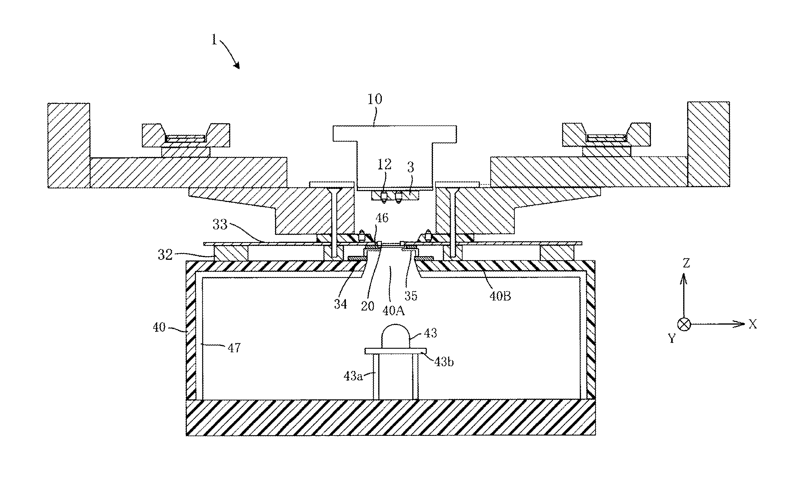
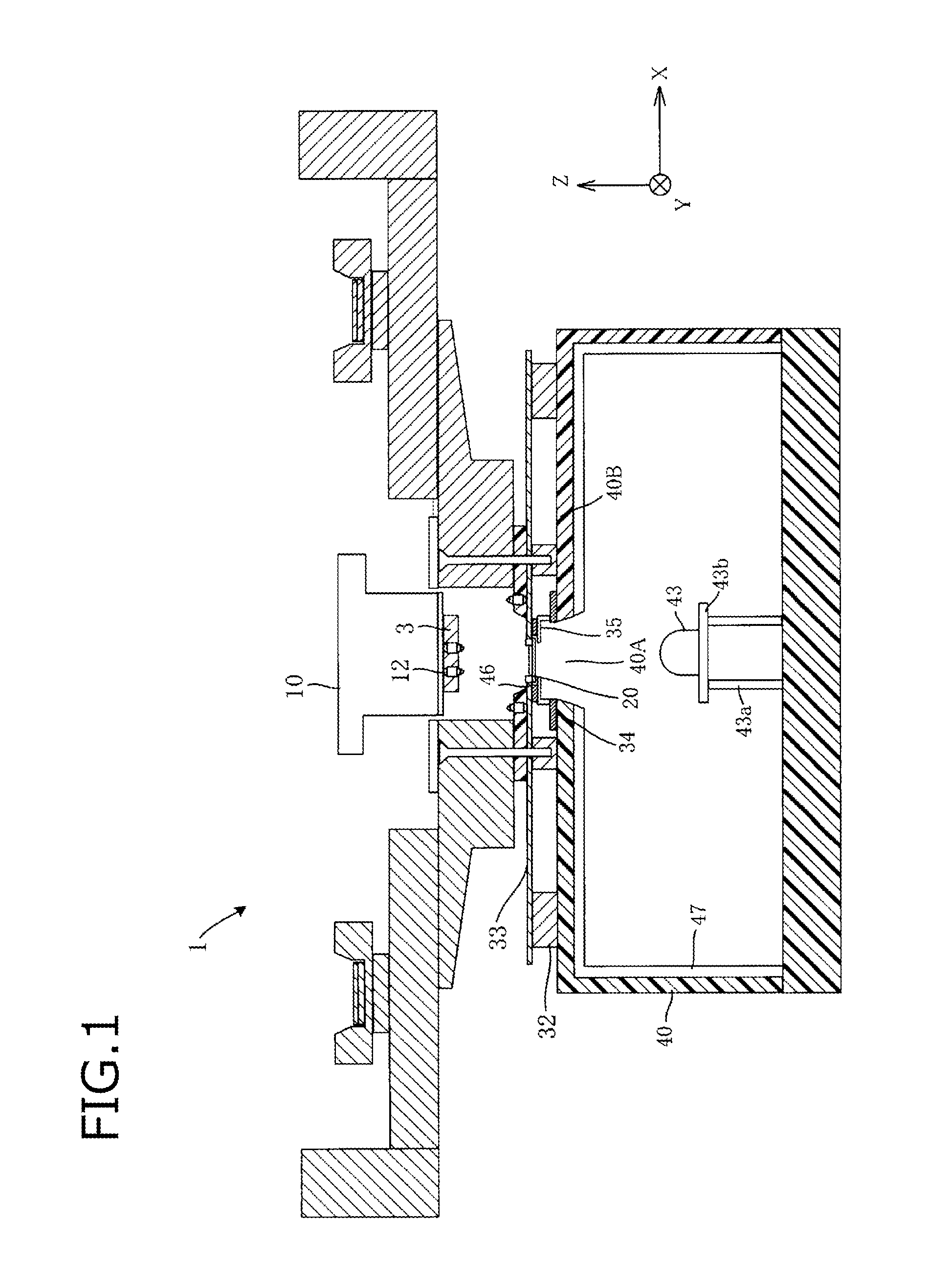
[0137]FIG. 16 is a sectional view showing an example configuration of part of a testing device 1B including the placement stage 20G according to the fourth embodiment. The testing device 1B is not equipped with the anechoic box 40 shown in FIG. 1 and is equipped with a radio wave absorbing body 44, an acrylic plate 45, and a measuring device 48. Constituent elements having the same ones in the testing device 1 shown in FIG. 1 or the placement stage 20G shown in FIG. 13 will be given the same reference symbols as the latter and descriptions therefor will be omitted or simplified.
[0138]The radio wave absorbing body 44 absorbs radio waves reflected from the measuring device 48 and thereby reduces radio waves...
PUM
 Abstract
Description
Claims
Application Information
 - R&D
- Intellectual Property
- Life Sciences
- Materials
- Tech Scout
- Unparalleled Data Quality
- Higher Quality Content
- 60% Fewer Hallucinations
Browse by: Latest US Patents, China's latest patents, Technical Efficacy Thesaurus, Application Domain, Technology Topic, Popular Technical Reports.
© 2025 PatSnap. All rights reserved.Legal|Privacy policy|Modern Slavery Act Transparency Statement|Sitemap|About US| Contact US: help@patsnap.com